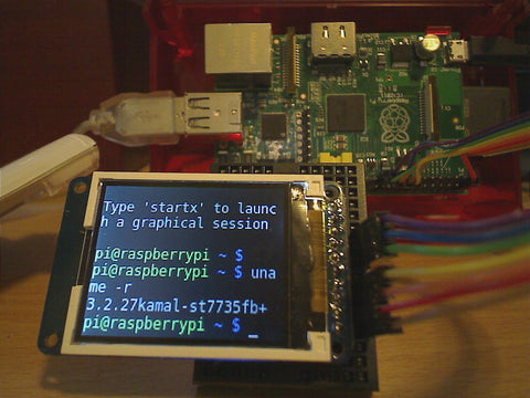
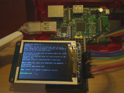
I've been experimenting with tiny 1.8" TFT LCD display modules from Adafruit and SainSmart as displays for the Raspberry Pi.
After a good bit of Linux kernel hacking on a driver for the ST7735R LCD controller chip, I got them to run as as the Pi's console device.
Video demos of the whole thing in action:
Photos of standard framebuffer apps running on the display: fbterm in a couple of font sizes, and mplayer playing a video clip at 24 fps


The 1.8" TFT LCD SPI-bus display modules available from Adafruit and SainSmart are functionally equivalent, except that the SainSmart unit can be driven at a much faster SPI bus rate than the Adafruit (32 MHz vs. 4 MHz in my testing). Fabien Royer has shown that this is due to a slow level shifter in the Adafruit unit.
The original st7735fb kernel driver was by Matt Porter, and was enhanced by Lady Ada, Neil Greatorex, and myself. I started with Neil's proposed version of Matt's st7735fb driver, which I extracted from Lady Ada's raspberrypi kernel repo. I applied Neil's version to the current raspberrypi 3.2.27+ kernel, then I made multiple enhancements to the st7735fb driver (and fixed a glitch in the bcm2708 SPI driver). I've since collaborated with Neil to develop further enhancements, and ported the driver to the upcoming 3.6.y Raspberry Pi kernel.
Technical Details
Wiring
The wiring connecting the Raspberry Pi to the display module is as follows (or use a carrier board as shown below):
| RasPi P1 header | Adafruit 1.8" TFT | SainSmart 1.8" TFT |
|---|---|---|
| 5V Power | LITE | |
| MISO | ||
| GPIO 11 (SCLK) | SCK | SCL |
| GPIO 10 (MOSI) | MOSI | SDA |
| GPIO 8 (CE0) * | TFT_CS | CS |
| CARD_CS | ||
| GPIO 24 ** | D/C | RS/DC |
| GPIO 25 ** | RESET | RES |
| 5V Power | VCC | VCC |
| Ground | Gnd | GND |
* My version of the st7735fb_map driver allows either CE0 (SPI 0.0) or CE1 (SPI 0.1) to be configured. ** My version allows the configuration of any GPIO pin for D/C and RESET. *** Since I'm not using the MicroSD card device on the back of the display modules, the remaining pins are left unconnected.
Clone my raspberrypi-linux repo
Clone my raspberrypi-linux repo, then select either the 3.2.27-based branch or the 3.6.y-based branch (run 'uname -a' on your Pi if you're not sure which you need):
$ git clone git://github.com/kamalmostafa/raspberrypi-linux.git
$ cd raspberrypi-linux
$ git checkout rpi-3.2.27+kamal-st7735fb
      -- OR --
$ git checkout rpi-3.6.y+kamal-st7735fb
Configuring the kernel build
The new ST7735FB driver needs to be enabled in your kernel build configuration. The drivers can be built as loadable modules or as built-in drivers (the built-in method is shown here):
- Cross-compiling?
- If you're cross-compiling this kernel, say on an x86 Linux host system,
- then add your cross-compiler settings to each "make" line below, for instance:
- $ make
- bcmrpi_defconfig
Create your initial build .config file (using this or some other method):
$ make bcmrpi_defconfig # ... or something else to create .config
Then customize your .config file, as follows:
$ sed -i  /CONFIG_FB_ST7735/d    .config
$ sed -i  /CONFIG_SPI_BCM2708/d  .config
$ make oldconfig
You will be prompted to select several options about your ST7735 panel configuration. Answer those as shown below, or type '?' for as short description of each option.
  BCM2708 SPI controller driver (SPI0) (SPI_BCM2708) [N/m/y/?] (NEW) Y
    ...
ST7735 framebuffer support (FB_ST7735) [N/m/y/?] (NEW) Y
ST7735 'red tab' panel type? (FB_ST7735_PANEL_TYPE_RED_TAB) [Y/n/?] (NEW) Y
ST7735 panel has reversed RGB? (FB_ST7735_RGB_ORDER_REVERSED) [N/y/?] (NEW) N
(or Y if red and blue are reversed)
  ST7735 framebuffer mapping to GPIO/SPI (FB_ST7735_MAP) [Y/n/m/?] (NEW) Y
  ST7735 RST gpio pin number (FB_ST7735_MAP_RST_GPIO) [-1] (NEW) 25
  ST7735 D/C gpio pin number (FB_ST7735_MAP_DC_GPIO) [-1] (NEW) 24
  ST7735 SPI bus number (FB_ST7735_MAP_SPI_BUS_NUM) [0] (NEW) 0
  ST7735 SPI bus chipselect (FB_ST7735_MAP_SPI_BUS_CS) [0] (NEW) 0
  ST7735 SPI bus clock speed (Hz) (FB_ST7735_MAP_SPI_BUS_SPEED) [4000000] (NEW) 4000000
(or 32000000 for SainSmart)
  ST7735 SPI bus mode (0, 1, 2, or 3) (FB_ST7735_MAP_SPI_BUS_MODE) [0] (NEW) 0
Now "make" and install your kernel as usual. (Unsure about the install procedure? Try Mark's tutorial for more details).
Console and login session with fbcon/getty
If you build the st7735 driver pair as built-ins (as shown above) you can add these options to the end of the line in /boot/cmdline.txt to map tty1 to the panel. The usual console kernel boot messages and the normal tty1 getty login will then appear on the panel. (See the fbcon documentation for more details):
fbcon=map:10 fbcon=rotate:1 fbcon=font:ProFont6x11
Note that con2fbmap also works; it can be used to dynamically remap the console tty's after boot.
Using the panel with mplayer
You'll get best performance by pre-scaling your movie down to the panel's native 128x160 resolution. Example:
$ mplayer -vo fbdev2:/dev/fb1 -x 128 -y 160 -zoom yourmoviefile.mp4
Alternate login session method with fbterm
The st7735fb driver supports fbcon which attaches the display as tty1 and/or other VT's so the standard getty login will appear without any additional configuration. The following alternate method using fbterm also works, but is more complex to configure.
To use fbterm instead of the standard fbcon/getty login session, create the following fbterm-login script and modified /etc/inittab to launch that instead of getty on tty1:
/sbin/fbterm-login
#!/bin/bash
# example: fbterm-login fb1 tty1
export FRAMEBUFFER=/dev/$1
exec /usr/bin/fbterm -r 1 -- /bin/login < /dev/$2
modify /etc/inittab ...
# 1:2345:respawn:/sbin/getty --noclear 38400 tty1
1:2345:respawn:/sbin/fbterm-login fb1 tty1
The rotation and font size of the terminal session can be changed by adjusting the fbterm -r 1 command line switch, or adding e.g. -s 5.
Texy "Pi TFT Shield" carrier board
This "Pi TFT Shield" carrier board available from Texy provides a convenient way to mate a 1.8" TFT panel module to the Raspberry Pi:

The board supports multiple different 1.8" panel pinouts including Adafruit and SainSmart, and sports mounting pads for three GPIO buttons. Very nice!


1 comment
This is a great project. Now I have a LCD screen using 7789 chips. I want to consult how to change the initialization in the program. Look forward to reply, thank you!