Building a Topographical Map with a CNC
Inspiration Hits
I wanted to work on a project that would push the limits of my CNC work so far, and a topographical map is something I’ve had my eye on for a while. This idea was the perfect dive into more complex pieces. And I am really glad I did.
Without a client’s specifications to match, I was able to pick any area I desired. I proposed to my wife on a vacation in Gatlinburg, Tennessee in the Smoky Mountains so it is a special spot for us. The terrain of this area has varying elevations with peaks, valleys, and everything in between, so it was a perfect region to work with.
Materials
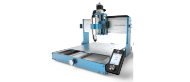
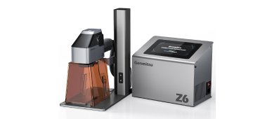
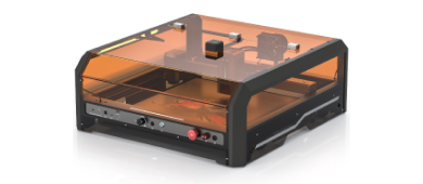
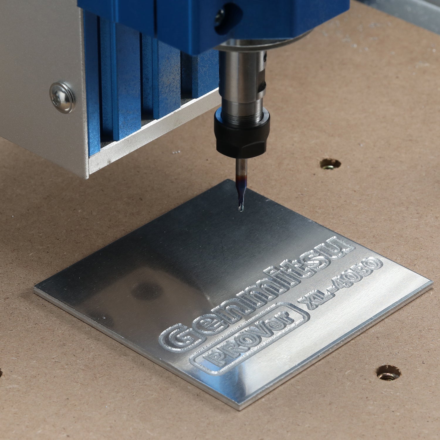
- Genmitsu PROVerXL 4030 CNC Machine (6060 extension optional)
- Terrain STL file
- CAD Software
- MeshCAM
- ¼” 2 flute downcut spiral bit
- 1/16” tapered 2-degree ball-nose bit
- 7“ x 7“ x 2 1/2” block of Ambrosia Maple wood
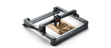
- Optional: Laser engraver
Time to Create
This task took some prep work to find the exact size and aspect ratio of the area I wanted to showcase. I began with the website jthatch.com to work out what area I wanted on my project. This site is very user-friendly, with an exact coordinates locator for anyone that knows them or a movable map to select the desired location. Instructions are included on the web page to aid in adjusting all aspects of the file such as depth, height, width, scale, and more.
I selected a 1:1 square area, showing the majority of the city of Gatlinburg, allowing for the most detail in elevation present and highlighting the adventure it is to hike in this region. I finalized my selection and downloaded the file to then open in a cloud-based CAD software, Tinkercad. Scaling and updating the files are the site’s best features for my needs.
I input my depths, stock, z-height and location, as well as set the roughing and finishing pass by transferring the file into MeshCAM. For this scale, I used a quarter-inch 2 flute downcut bit roughing pass to remove the bulk of the material and a 16th inch tapered 2 degree ball-nose bit in a parallel finishing pass.
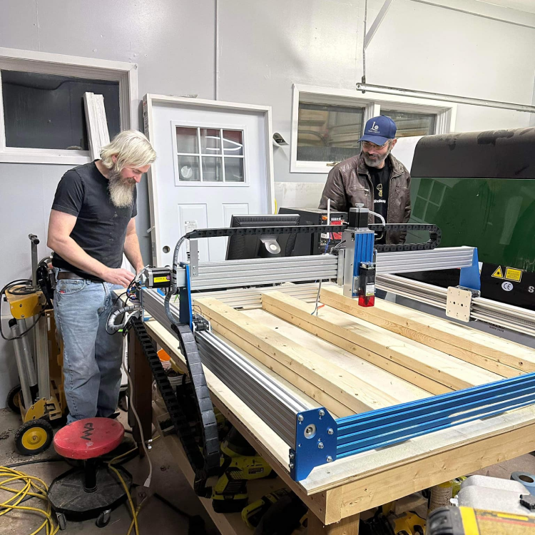
My go-to trick for setting up material for the CNC is to layer masking tape on the spoilboard and the material, then bond them with CA glue and activator. The masking tape removes without any damage to either product and the glue holds everything in place without clamps or other accessories. Once the wood was in place and the bit was zeroed up, I was ready to run the code and let the Sainsmart 6060 do its job. The run time for this map was approximately four and a half hours.
For this project, I wanted to add the name of the location and coordinates to the piece, so I purposefully left a flat area in front, at a lower height than the map portion to put this detail. I used a laser-engraver for this extra step to give a clean, contrasting look.
Better Luck Next Time
For future projects like this, I would add a finishing step of sandblasting the overall areas, allowing me to get into the nooks and crannies of the map while leaving the most detail through a sanding process. For any similar pieces, I would suggest to others: ensure the height of the wood does not crash into the collet on your router.
Links and Sponsors
jthatch.com/Terrain2STL
Tinkercad.com
Sainsmart