Written by Graham Bland. You can find me on the Facebook group SainSmart Genmitsu CNC Users Group All comments, suggestions and corrections are welcome.
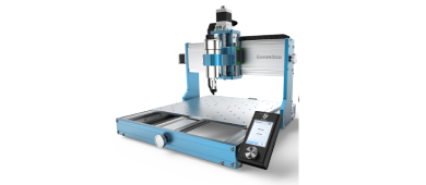
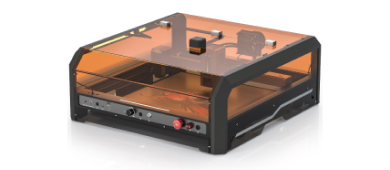
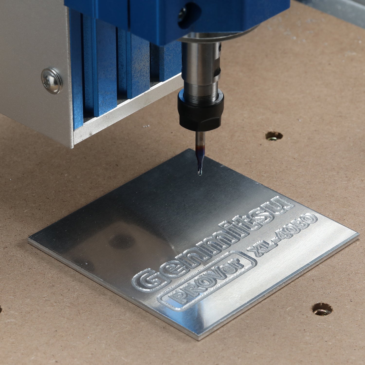
This is Genmitsu 3018-PROVer V2 CNC Router, currently available for $349, I am reviewing this partly based on that, if I was paying $1,000 or more the criteria would be a bit different! Anyway, it is a small, entry-level router.
Box weight is 11.3Kg which is quite full and very well packaged. Most of the unboxing time was spent carefully prising out the frame and gantry components from their cocoon! Some unboxing photos:

I could add more pictures but there is no real point!

The out-of-the-box photo above does not show the side plates, I had put them to the side during the unboxing and I am not going to dismantle them to take a new photo! You can see them in the second unboxing photo above.
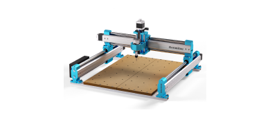
It’s a moveable bed router, (the bed moves on the Y axis under a gantry that is fixed in position) The other type is a fixed bed where the gantry moves over the bed on the Y axis.
What you get
The frame and bed are entirely aluminium and steel construction, pre-assembled and pre-wired.
|
|
The gantry is also pre-assembled, all aluminium and steel with a plastic Z-axis assembly and motor mount. The control board is already mounted and all the limit switches and wiring are pre-installed.
|
| The Z axis is driven by a Nema17 stepper motor driving a leadscrew along two guide rods. The motor mount takes a standard 44mm 775 spindle motor. |
| The power supply is an automatically switching 110/240V 50/60Hz 2.5Amp input providing a 24V 4Amp output. This has a high start-up current and so is suitable for the 20k motor upgrade. |
| The spindle motor is a 775 type (44mm diameter) capable of 9,500RPM with a pre-installed ER11 collet. |
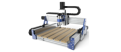
| Side plates keep the dust and chips produced from spraying out of the sides. |
| 4 adjustable work clamps. |
| 3-axis 32-bit Grbl controller board. |
| USB cable. |
|
Upgraded Offline controller with 1.8” colour screen.
|
| Z-Probe, 3 pins with indicator LEDs. |
| A set of V20 bits. |
| Assembly tools and collet spanners. |
| Printed User Manual. |
All the axes have pre-installed aluminium manual adjustment knobs.
Control Board

Worth a separate mention as this is a 32-bit Grbl board using a 32-bit ARM Microprocessor rather than the ‘normal’ 8bit ATMEL processor. This is pre-mounted on the rear of the Gantry with a lot of the wiring pre-installed.
Connections:
- USB socket (type D, cable provided).
- Offline Controller (10 Pin)
- MPG port (which should take the SainSmart CNC Handwheel controller, previously for the MX3 only! This has NOT been reviewed by me).
- 3-pin Z-Probe Connector NOTE: The Z-Probe connector is a 3-pin, not the normal 2-pin. But the Probe is also different as it looks to have flashy lights on it, more later.
- 24V DC input.
- 3Pin 12V Laser PWM socket.
- 2-pin Air assist control socket (For Future use??)
- X, Y, and Z Stepper motor sockets
- 6 Limit switch connectors (only 3 used, each axis has the limit switches wired in parallel)
- 2-pin E-Stop socket
It does expose the ‘Air assist’ pins which most 8-bit boards do not, but the Door switch is not exposed, this can be a useful safety feature if building an enclosure, but then nearly all 8-bit boards do not expose either of these pins either.
It reports running Grbl 1.1f, Grbl for ARM32 Version:ARM32 V2.1
The control board uses an exposed heatsink and does not require or have a cooling fan.
Assembly
It’s pretty simple, including the feet (4) and the side plates (8) there are only 22 bolts to attach everything together! Follow the Manual, it’s pretty good. I see no point in adding pictures of my own for the assembly process, the illustrations in the manual are good and my pictures would add nothing.
As it is largely pre-assembled and pre-wired. The main task is connecting the gantry to the frame, this uses 4 bolts on each side into pre-drilled and tapped holes at the side of the base assembly.
Bolt-on the side plates and plug in the wiring connectors to create a working router.
Assembly should not take any more than an hour at the maximum, including tea breaks, even if done carefully.
Assembly Hints
- I normally check all the bolts and screws on any pre-assembled parts for tightness and check everything is square, things can become loose in shipping! Also, check any wiring connectors are fully seated into their sockets. I do suggest that you check any router before you assemble it, screws can be tightened before and during assembly, and it’s a lot more difficult to diagnose and fix any problems like this once you start to use it. But in this case, I didn’t find any problem with the frame or gantry but one connector to a limit switch had come partly loose.
- It is also good practice to check all holes for any obstructions such as packing materials or in the spoil board clamping holes for any remaining swarf. It is much easier to remove any before assembly.
- When securing the gantry to the bed frame the gantry plate obscures the holes on the side extrusion. Make a pencil mark on the top of a base side extrusion 31 mm from the inside of the back plate, hold the gantry vertical with the rear edge on the pencil mark and align the bottom of a gantry side with the bottom of the base side. This should put the screw very close to the hole making it much easier to find screw holes. Once one screw is in the rest are much easier!
- Most of the bolts had a spare, so don’t be too worried about having bolts left over.
- The two limit switches are unused.
The finished item:

Z-Probe

This one has 2 LEDs, the blue one lights when it is connected and ready. When contact is detected the red lights and the blue one is extinguished. It uses a 3-pin connection which means it is not compatible with 8-bit GRBL control boards. The cables are very flexible allowing it to stay where it is put when probing which is very useful.
Mine measured a thickness of 12.2mm using calipers, yours may be slightly different due to manufacturing tolerances.
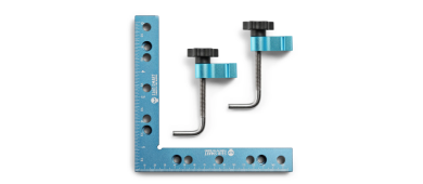
Clamps

The Bed is a solid 6mm thick Aluminium plate with M6 drilled and tapped holes to take the standard 6mm screw on the clamps. The spacing of the holes is shown in the picture above.
The clamps are basic but they allow effective clamping of materials up to ~2cm (0.75”) thick. If you are going to use thicker materials then you are going to need better clamps! SainSmart has these as do others and there is always double-sided woodworking tape or painter's tape and super glue.
Offline Controller

A Genmitsu Upgraded offline controller is included. This has a 45mm (1.8”) color screen and buttons for jogging and navigating the menus.
The offline controller can be used as a replacement for a PC and USB cable when the router is placed away from your PC. It provides all the features needed to set up and control the router and takes a micro SD card (provided) on which your Gcode files can be saved and the offline controller will send them to the router just like a PC-based Gcode sender program such as Candle or UGS.
NOTE: do not connect the USB cable and the Offline controller at the same time, the commands can conflict with unpredictable results!
Read more Part 2 here, more blogs updating soon, please subscribe to our newsletter.
Compare with Genmitsu 3018-PROVer CNC Router