
Written by Graham, find me on the Facebook group SainSmart Genmitsu CNC Users Group
This is a guide as to how to set it up. It covers some tests, optimising some Grbl settings and making, surfacing and engraving a Spoilboard.
Full designs and Gcode files for the Spoilboard are included. For my assembly hints please see my review.
I am using Candle here as the GCode sender to connect to the router, other options are available but Candle is free and simple to use.
The target audience here is a total novice using their first router. If some parts seem a little long winded to you then just skip the details.
Saving the Grbl Settings
The first thing I always do is make a backup copy of the Grbl settings, also after making any significant changes I always make another backup just in case.
In the Candle console pane send a $$ command, it will respond with a list of all the current Grbl $= settings. Copy these and paste into a text editor and save the file somewhere (4040 Original Settings.txt is a good file name).
Aligning the Y axis
The 4040 has dual stepper motors to drive the Y axis. Before powering on the alignment of each side of the Y axis must be accurate, if not the gantry will be at an angle to the X axis and may stick or bind as it is moved. This should be re-checked if;
- The router is moved.
- After any cut where there may have been missed steps.
- Limit switches have been activated during a cut, not homing.
- The Emergency stop button has been used.
- One or both Y axis handwheels have been turned by hand.

It is a simple process, but essential to the proper operation of the router.
- Power off the router.
- Place a spacer between the rear carriage assemblies and the back of the router. (You don’t have to use the spacer; you can just align so the gantry touches the rear frame but I find the spacer easier.)
- Using the manual handwheels on the Y axis steppers move the gantry to the back of the router turning the handwheels evenly. If it starts to bind check the alignment and adjust it using the handwheels separately until it moves freely again.
- Adjust the handwheels so that the Y axis carriages touch the spacer with a light but equal force at each side.
- Remove the spacer.
Simple tests
Once it is assembled there are some simple tests which are worth performing. These apply to most similar routers regardless of the manufacturer or model. They are pretty basic tests and are designed to detect any assembly errors and possible errors with cabling. It is very rare but always possible that there is an error in a cable somewhere, in my case it’s more likely that I forgot to plug one in!
Install Candle according to the User Manual, start Candle, connect the USB cable and turn the router on, (the order does not matter, but if the router is not powered on the axes will not move!) and connect Candle to the router.
Limit Switches
Just to make sure they all work unlock the router and then trigger a limit switch manually; the router will return an Alarm 1 error. If it does not then there is a problem with the limit switch or more likely the wiring, check all the connections.
Reset the router, unlock and trigger the next switch. Repeat until all 6 switches have been tested and are working.
Some of the limit switches are well hidden to give maximum movement! Y axis switches are on the left hand carriage the rear in the carriage mount, front easier to get to. If you find them difficult to trigger manually use the jog controls to slowly move into them. The photo shows the switch locations within the Y axis rear mount.

Movement
Either manually or using the jog controls move each axis along its full travel. It should move freely without any signs of binding, if one does start to bind using jogging the ‘note’ the stepper motor makes will change.
If you hit a limit switch just reset, unlock, jog away from the triggered switch and continue on the next axis.
Calibration
Simply check that if you tell an axis to move by 100mm (for example) it does actually move 100mm. It is very unlikely that this will be a problem.
On the X and Y axis place a ruler along each axis in turn, position the router at Zero (use a V bit close to, but not touching, the ruler for accuracy) and jog 100mm. If the router does not move 100mm there is a problem.
Repeat for the Z axis, but try 50mm of movement. Measuring this is more difficult on the vertical.
It should be precise but for the moment close is good, this is not a precise method of measurement, if it looks to be out then think about calibrating the axis, but that requires a lot more effort than just measuring along a ruler once.
Homing
Run a homing cycle, by default the router should go to the front, top, left position, and back off from the limit switches so they are no longer triggered and be ready to use.
Coordinate Systems
Just a quick note, a Grbl router has two sets of coordinates for any position the Machine coordinates and the Work Coordinates. From the origin as the spindle/laser moves the coordinate will change.
- The X axis shows -ve to the left and +ve to the right
- The Y axis shows -ve to the front and +ve to the back
- The Z axis shows -ve down and +ve up
Using the default home position, the X and Y axis will be in a positive space with zero at the front left, the Z axis will be in a negative space with zero at the top. If you set the home position to the back right then The X and Y axes will be in a negative space.
Machine coordinates are initialised by running a homing cycle, by moving into the limit switches at the end of each axis in turn the router establishes the machine coordinate for that axis. If you don’t fit limit switches or do not run a homing cycle the machine coordinates are zero wherever the router happened to be when you turned it on or reset it.
Work Coordinates are set to zero by using the Zero X Y and Z commands, the same +ve and -ve directions apply.
Measuring maximum travel
I like to measure the available movement on each axis accurately. It can be useful to know by displaying the Grbl settings what the actual maximum travel values are and it is also needed to use soft limits or drill and engrave a Spoilboard accurately.
From the home position note the machine coordinates for the axis in my case 0,0,0 then jog each axis in turn until the limit switch is triggered at the other end of the axis. The absolute difference between the start and end machine coordinates is the maximum travel on that axis.
These values are stored in the Grbl $130-132 values for the X, Y and Z axes. I do suggest knocking off 0.5m from each value to ensure that the limit switches are not triggered.
My cutting area measures 434 x 403.5 x 77mm (17.09 x 15.89 x 3.03”)
GRBL Settings
A lot of these are personal preferences but I think they make sense. NOTE: ALL settings use the metric system! It doesn’t matter if you are using inches or not ALL settings use mm, mm/min or mm/sec2 for accelerations as and if appropriate.
NOTE: You will see some values for an A Axis, the 4040 board has support for not only the X, Y and Z axes but also an A axis, normally used for a rotary attachment along the X axis. At the time of writing, I have never used one and don’t have one so these are ignored here.
Stepper motor lock and Pulse ($1)
$1 controls the time in ms after which the steppers will be unlocked. 255 is the maximum value and if set to 255 they will be permanently locked as long as the power is on.
If the steppers are locked then they will resist movement. If you are performing tool changes then keeping the steppers locked will help prevent movement, the downside is that using the manual knobs to move an axis should never be attempted with the power on and the power consumption of the steppers will not fall when idle.
Report in inches ($13)
Grbl operates in mm, if you set the movement units to inches in Grbl then the first thing it does is convert them to mm. By default any position reports it sends back are in mm, however you can tell it to report in inches by the $13 setting. This should mean that your Gcode Sender will display things like coordinate positions in inches rather than mm. BUT as I work in mm I have not tried this, however if you habitually use inches try setting $13=1.
This does not affect any units set and used in a Gcode file or other commands, just the units Grbl will report in.
Limits and homing control ($20-27)
There are two types of limits used to prevent the router from trying to move out of the cutting area, hard and soft, this prevents the nasty grinding noises as the stepper motor tries to force an axis past its limit of movement. You can use one or both or none, however limits can only be used if a homing cycle has been run which requires that limit switches are fitted.
Soft limits ($20)
Each movement command is checked before it is executed, if it would result in the router moving past the maximum travel limits ($130-133) on each axis the router stops before the command is executed.
Soft limits are controlled by $20, set to zero they are disabled, set to 1 they are enabled.
To use soft limits effectively the maximum travel distances ($130-133) must be set accurately.
There can be some problems using soft limits, mainly when using a Z-probe, the Z Probe commands include a ‘how far should I travel before I encounter the probe’ distance, this depends on the position at the start of the probing command, if the maximum would exceed the machine limits an error will be reported.
Hard Limits ($21)
Quite simple, when the router triggers a limit switch at the end of any axis it will stop. The machine and work position will then be inaccurate as there may have been instructed movement which has not completed.
Hard limits are controlled by $21, set to zero they are disabled, set to 1 they are enabled.
Homing ($22-26)
By default homing is enabled ($22=1) to disable it set $22=0. Homing must be enabled and a homing cycle must have been run to use Soft limits.
Homing is started by sending a $H command to the router, all Gcode senders will have a button to do this automatically.
The homing process is:
- Move from the current position towards the corner set by $23 at the homing seek rate set by $25. The Z axis is homed first.
- When a limit switch triggers:
- Back away a little to clear the limit switch
- Re-approach the switch at the slower Homing feed rate ($24) until the switch is triggered again, the slower approach should give a more accurate reading of the position than a high speed crash.
- Back off by the Homing pull-off.
- Note: Some GRBL boards will record the zero position at the point the switch was triggered, some will record the zero position at the point after the homing pull off distance. The 4040 records it after the pull off so the coordinates will be all zeroes.
- If there is an error such as a limit switch cannot be found or the pull off failed to un-trigger a switch an alarm condition will be raised and Homing will fail.
Homing Direction Invert Mask ($23), Where does it home to?
You can select where (which corner) the router home position is. This is controlled by the Homing Direction invert ($23) it takes a value of 0-7 which indicates the corner as shown. $23=3, the default setting, specifies the Top Left Front. To change the corner change the $23 value. I strongly suggest that only the top corners (0-3) are used to keep the bit away from clamps, stock and the bed.
My personal preference is Back Right Top or $23=0, it gives me full access to the bed and any stock on it.

Homing Feed ($24)
Increase to reduce the homing cycle time but this is only going to apply when the axis is already very close to the limit switch so it’s not going to make much difference. IMHO the default of 100 mm/min is too fast so I have changed it to 25mm/min.
Homing Seek ($25)
Increase to reduce the homing cycle time but remember that the seek phase will end on each axis by crashing into the limits switch at full speed. Too fast and you will potentially cause damage over repeated homing cycles. Mine left at the default.
Homing debounce ($26)
When a mechanical switch is triggered the contacts can bounce on and off for a short time while it settles down. The debounce is the time (in ms) to wait to let the switch to settle down before reading it again. Makes virtually no difference to the speed of the homing cycle, however 50ms should be sufficient for any debounce interval so mine is set to 50ms.
Spindle motor/Laser power settings ($30-32)
Grbl holds the maximum and minimum rotation speeds for the spindle, $30 and $31. These are also used for laser power when a laser is connected.
Spindle/Laser Max ($30)
The default 775 spindle motor has a ~9,000 RPM maximum speed, I set mine to 9,000 RPM. If you change the motor modify this to the new motor setting, a 300W 52mm motor is normally ~12,000 RPM.
For a Laser the power is controlled by a PWM signal, a value from 0 to 255, or 256 possible values. When using a Laser I change this to 1000, personal preference. This must match the Maximum power setting in your laser software!
Spindle/Laser Min ($31)
The default 775 spindle motor has a ~1,500 RPM minimum speed. If the spindle speed is set too low when cutting the spindle motor can stall which in turn can damage the control board. So I set mine to 1,500 RPM.
When using a Laser I change this to zero.
Laser Mode ($32)
Tells Grbl if you are using a spindle motor ($32=0) or a Laser ($32=1). This needs setting correctly when you switch between them.
Steps per mm ($100-103)
A stepper motor will move by a certain angle each time, this is a step. The number of steps per mm will not only depend on the stepper motor but also on the gearing used (leadscrew) on the axis.
Only change these if they are corrupted or after performing an accurate calibration of the axis. Mine left at the default.
Max Rate ($110-113)
For each axis how fast it can be moved. If Grbl sees a requested Feed rate (Fxxx) that exceeds the value for an axis then this value will be used instead to prevent the router from overloading and missing steps.
This does not mean the router can make a cut at this rate, just that it can move without any load at this speed.
This would need a set of tests to change the speeds reliably so mine for now are left at the default.
Acceleration ($120-123)
To move anything you need acceleration, going from rest to 2,000 mm/min instantaneously is physically impossible it’s all about momentum. Think of a high powered sports car, put your foot down and it may accelerate rapidly but will not go immediately to 100mph.
Grbl uses these values to determine how fast it can speed up and slow down the movement to achieve a movement rate. The maximums depend not only on the router but also on the mass of the spindle motor. Put on a 200g Laser and you will be able to accelerate faster, change that for a 2kg spindle motor and it’s going to be slower.
Faster accelerations will reduce machining times, and if using a Laser it can help to reduce overburn at the corners. Set them too high and the router will be overwhelmed, miss steps and your work will be ruined. For now I am leaving these at the defaults until I can run some comprehensive tests.
Maximum Travel ($130-133)
Used by Soft Limits, (also for the maximum travel distances during homing with a 1.5 multiplier) These are the maximum absolute (No sign, if an axis moves from 0 to -100 or 0 to 100 the travel is just 100) distances in mm each axis can safely move. I have set the XYZ values to my measured movement distances on the XYZ axes which are $130=434, $131=403.5, $132=77.
Other Settings
Some of the settings in the $0-12 range are more for the router designer and builder rather than the user. I am ignoring these here.
Saving your changes
There is no need on the router, if you change a setting it is automatically saved. I do strongly suggest keeping a copy of your current settings though, these could be needed if your router board fails and you have to replace it, or if you are changing your setup for any reason and want to go back to before you started changing things. Just send a $$ command and copy and paste the settings to a text file. (4040 Current Settings.txt is a good file name)
Restoring settings
Grbl keeps a separate copy of the factory settings, if necessary, the factory settings can be restored by sending a $RST=* command. This will restore ALL settings to the factory values. However these may not be what you want so opening your 4040 Current Settings.txt and change each setting which is different from the $$ display using separate $xx=yyy commands.
Settings Summary
These suggested values are my preferred values when using a standard 775 motor, yours may be different.
|
$ |
Category |
Description |
Default |
My Values |
Units/Range |
|
0 |
Board |
step pulse |
10 |
10 |
µsec |
|
1 |
Board |
step idle delay |
25 |
25 |
msec |
|
2 |
Board |
Step port invert mask |
0 |
0 |
0-7 |
|
3 |
Board |
Dir port invert mask |
4 |
4 |
0-7 |
|
4 |
Board |
Step enable invert |
0 |
0 |
0,1 |
|
5 |
Board |
Limits pin invert |
1 |
1 |
0,1 |
|
6 |
Board |
Probe pin invert |
1 |
1 |
0,1 |
|
10 |
Reporting |
status report mask |
3 |
3 |
1-3 |
|
11 |
Board |
junction deviation |
0.010 |
0.010 |
mm |
|
12 |
Board |
arc tolerance |
0.002 |
0.002 |
mm |
|
13 |
Reporting |
report in inches |
0 |
0 |
0,1 |
|
20 |
Limits |
soft limits enable |
0 |
0 |
0.1 |
|
21 |
Limits |
hard limits enable |
1 |
1 |
0.1 |
|
22 |
Homing |
homing cycle enable |
1 |
1 |
0,1 |
|
23 |
Homing |
homing direction mask |
3 |
0 |
0-7 |
|
24 |
Homing |
homing feed rate |
100 |
25 |
mm/min |
|
25 |
Homing |
homing seek rate |
500 |
500 |
mm/min |
|
26 |
Homing |
homing debounce |
250 |
50 |
msec |
|
27 |
Homing |
homing pull-off |
2.0 |
1.0 |
mm |
|
30 |
Spindle/Laser |
maximum spindle speed |
10000 |
9000 |
Rpm/Power |
|
31 |
Spindle/Laser |
minimum spindle speed |
0 |
1500 |
Rpm/Power |
|
32 |
Spindle/Laser |
laser mode enable |
0 |
0 |
0,1 |
|
100 |
Board |
X axis steps/mm |
800 |
800 |
|
|
101 |
Board |
Y axis steps/mm |
800 |
800 |
|
|
102 |
Board |
Z axis steps/mm |
800 |
800 |
|
|
103 |
Board |
A axis steps/mm |
177.777 |
177.777 |
|
|
110 |
Movement |
X axis Max rate |
2000 |
2000 |
mm/min |
|
111 |
Movement |
Y axis Max rate |
2000 |
2000 |
mm/min |
|
112 |
Movement |
Z axis Max rate |
2000 |
2000 |
mm/min |
|
113 |
Movement |
A axis Max rate |
1000 |
1000 |
mm/min |
|
120 |
Movement |
X axis acceleration |
20 |
20 |
mm/s2 |
|
121 |
Movement |
Y axis acceleration |
20 |
20 |
mm/s2 |
|
122 |
Movement |
Z axis acceleration |
20 |
20 |
mm/s2 |
|
123 |
Movement |
A axis acceleration |
20 |
20 |
mm/s2 |
|
130 |
Limits |
X axis Max travel |
400 |
434 |
mm |
|
131 |
Limits |
Y axis Max travel |
400 |
403.5 |
mm |
|
132 |
Limits |
Z axis Max travel |
80 |
77 |
mm |
|
132 |
Limits |
A axis Max travel |
9999 |
9999 |
mm |
From this point on I am using the modified Grbl settings!!!!
Setting up the Z-Probe
The 4040 uses a 3 pin Z-Probe which has 2 indicator LEDs, the blue one lights when the probe is plugged in, the red one when contact is made. Apart from that it is just a switch between the probe base and the bit.
The first thing to do is to accurately measure the thickness of the probe base, if you have an accurate set of callipers this is the easiest, just measure the thickness (in mm please). Sorry but a ruler is just not going to be accurate enough.
You can use the router to measure the thickness, it’s slightly tedious but is accurate and only has to be done once.
- Place a bit in the router, connect the Z probe and place the centre the of the probe base under the bit.
- Place a piece of paper on top of the probe base and SLOWLY jog the bit down until there is friction between the end of the bit and the paper, but the paper can still be moved. The final adjustments should be made using the minimum jog movements (0.01mm) and also move the paper around so you are not measuring on a place that has been ‘squished’.
- Note the Z axis machine coordinate, then jog the Z axis up a few mm to allow the paper and probe base to be removed.
- Now place the paper between the top of the stock (or bed) and go through the same process as in step 2.
- Note the new Z Axis machine coordinate. The height of the probe base is the difference between these Z-Axis numbers.

My probe base height is 12.1 mm, all following examples will use 12.1, substitute the value of yours for the 12.1
In Candle go to Service Settings and change the Probe Commands line to G21 G91; G38.2 Z-100 F250; G0Z1; G38.2 Z-2 F10; G92 Z12.1; G0 Z2
For more information on what this does please search for Z-Probes in the files section.
In UGS probing is controlled by the probe plugin, make sure the Z Touch plate thickness is set to 12.1 and the other settings are what you want.
Spoilboard
It has an MDF bed – Why fit a Spoilboard?
- I intend to surface the Spoilboard to leave a totally level bed, If I just surfaced the bed no surfacing bit would reach the edges of the bed, this would leave a step up to the edges making mounting of large stock tricky.
- Replacing the bed when it becomes worn would cost far more than replacing an MDF Spoilboard mounted on top.
- The bed is in two parts. Adding this over the top of the join will help the overall rigidity.
Design
I am going to use a piece of MDF secured to the bed using tape and superglue.
The next decision is the size of the Spoilboard.
Length is simple, I will be using a 25mm (1”) surfacing bit using the standard 775 spindle motor, so whatever the maximum Y travel + 10mm at each end is the length, in my case 403.5+2*10 = 423.5mm, I have rounded this up to 425mm (16.73”) for simplicity as the edges are still within range of the bit.
Width is even simpler; the bed is 2 pieces of MDF which when mounted measure 440mm wide. My measured cutting width is 434mm, with the size of the bit I could surface 454mm wide. To avoid the Spoilboard sticking out over the edges I am using 440mm as the width.

Material
I now use a quality MDF for my Spoilboards. Known in the UK as Medite it has a low formaldehyde content which means less harmful dust when inadvertently cutting it and less harmful fumes if the laser cuts it. It also has a higher moisture resistance than generic MDF. For the thickness 6mm (0.25”) is a good compromise, it lasts a while depending on the abuse it takes and reduces the maximum Z stock thickness by a minimum. As I do not have a ‘shop’ I rely on buying the material cut to size.
What you will need
Perhaps more precisely what I used, other options are available.
|
Item |
Description |
|
Surfacing bit |
SainSmart RB03A, 1/4'' Shank, 3-Flute, 1'' Spoilboard Surfacing (Note the ¼” shank you will need a ¼” (6.35mm) ER11 collet). |
|
Spoilboard |
440 x 425 x 6mm (17.32 x 16.73 x 0.24”) MDF (Two pieces) |
|
Painters tape |
3M Blue Painters tape 25mm (1”) |
|
Superglue |
I use Everbuild Superglue HV (as it has a 10-30 second set time) No activator. |
|
V Engraving bit |
20° V bit from the sample bit set supplied with the router. |
|
Machining bit* |
SainSmart 3.175mm (1/8”) 2 flute flat end from the MC40A set |
* Any straight edge 3.175 (1/8”) bit can be used, the holes are going to be 8 mm in diameter, the supplied Gcode is for a 3.175mm (1/8”) diameter bit. As the operation is making holes I do not recommend downcut or compression bits. Any lip left at the top will be removed by surfacing later.
Making one or making two.
As this is the first Spoilboard, there is no existing spoilboard fitted to the bed so I am making two at once, one on top of the other with the bottom piece acting as the spoilboard for the top piece. This will keep the bed pristine as the holes in the spoilboard have to be cut through and as the bed has not yet been levelled this will be below the bottom of the spoilboard.
If you are replacing the spoilboard then you can just make one.
Securing a spoilboard
If you are familiar with the Blue or Painters tape and superglue method skip this section.
You cannot clamp a spoilboard down! You could screw or bolt it to the bed, you could glue it directly to the bed, or you could tape it down.
Pieces of tape are stuck onto the bed, a matching pattern of tape is stuck onto the bottom of the spoilboard. Then superglue is applied, normally in a wavy pattern, to one of the tapes. Align them, press it down until the glue sets and the tapes are secured together. To remove it use something like a scraper to separate the tape from one of the surfaces, bed or spoilboard and remove the tape from both the parts.

Blue tape is a synonym for a better quality of masking tape than the cheapest paper stuff. The quality is important as then the tape sticks to the parts and the glue holds the tapes together without seeping through the tape. (Other colours are available!) Also the tape adhesive lasts a lot longer without drying out than cheaper alternatives.
Double sided tape, preferably woodworking tape, as it is made with a stronger adhesive than, for example, carpet tape can be used. But it can be thicker and more expensive than the Blue Tape method. Also I would suggest that you never cut through double sided tape as the adhesive will stick to the bit and clog it up. The superglue sets hard and is far less likely to adhere to a bit cutting through it.
Step 1 Join the pieces
Align the two spoilboard pieces and secure them together using blue tape and superglue. A bit of care is needed as it is a good idea to avoid taping the hole locations where possible.
The taping will be temporary so don’t go overboard, but it must be secure enough to take cutting one set of holes, removing from the bed, turning the spoilboards over and doing it all again! This is just what I used.
Now treat it as one spoilboard for the next few steps, just 12mm thick.

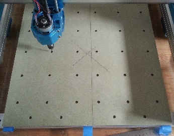
Step 2 Marking the work origin
Draw diagonal lines across the spoilboard, where they cross is the centre of the spoilboards and will be the XY work origin of the hole and engraving machining steps.

I have also added a line down the edge of the centre line of tape on the spoilboard and bed, this makes it easier to line up the tapes when applying them to the bed and spoilboard in step 3.
This needs to be fairly precise to align the slightly oversized holes being machined into the spoilboard with the existing holes in the bed. If for any reason you are using a different sized spoilboard, the X origin is in the centre of the bed on the X axis and the Y origin is 212.5mm from the front of the bed. It’s worthwhile checking this anyway.
Step 3 Align and fix to the bed
At this stage the joining of the bed and Spoilboard is temporary, it needs just enough to keep the spoilboards in place while the holes are cut, I am using only 3 pieces of tape, one down the centre of the Y axis and one at each edge on the bed and spoilboards.
Add the glue, align the spoilboards with the front and sides of the bed and press down.
Step 4 Machining the holes
Mount the 3.175mm (1/8”) bit in the spindle and set the XYZ zero point at the marked centre point of the Spoilboards.
Load and run the ‘4040 Spoilboard Cut Holes.nc’ GCode file to cut the holes. The holes will be cut through into the bottom spoilboard by 1mm to ensure that all the holes are cut through completely.
If there is any lip left on the top edges of the holes cut or sand this off to ensure the surface will be level with the bed, I find a paint scraper works well.
Step 5 Flip and repeat
Remove both pieces still attached to each other from the bed. If you want to make the second Spoilboard now (Might as well, everything is set up) flip the pieces, still connected to each other, over on the Y axis keeping the front at the front so that the already cut holes will be over the spoilboard holes and re-attach to the Spoilboard using another 3 lines of tape and glue as before.
Repeat the process to mark the work origin and cut the holes in the now top piece.
Step 6 Permanently fix a Spoilboard to the bed
Split the 2 boards apart, a paint scraper works well inserted under or between the tapes. Remove any masking tape glue overflow and lips on the holes at the bottom side. Set one aside for the future, apply tape to the other and the bed to ‘permanently’ fix it down. This time use a little more tape and make sure that one of the tape lines goes down the centre of the bed to help hold the two bed parts together. Make sure you do not cover any of the clamping holes on the bed or Spoilboard. If any holes are covered cut away the tape to leave them open.

I used 3 strips of 25mm tape down the centre to hold the Spoilboard to the 2 bed halves, making the centre joint as secure as possible. As for the others, I cheated by using the holes as alignment marks rather than measuring and drawing lines to make sure the tapes are aligned.
To help align the spoilboard I placed the clamping screws into the bed, then placed the spoilboard over the screws, check the holes over the entire spoilboard are aligned with the bed holes and push it down.

Secure the Spoilboard to the bed until the glue sets, I used the clamps to secure hold it to the centre area firmly over the spoilboard halves.
Step 7 Surfacing the Spoilboard
Fit the surfacing bit (RB03A 25mm (1”) flat end surfacing). The surfacing Gcode included requires a 25mm (1”) diameter bit.
NOTE: The surfacing work origin is at the back right of the bed. The easiest way to use this is to set the home position to the top back right position, $23=0 and home the machine. Then set the work origin XY at the home position and the maximum possible area will be surfaced.
Load the surfacing Gcode file ‘4040 Spoilboard Surface.nc’, the speeds, feeds… are set for the stock 775 motor. The Z-Zero ideally should be set to the highest point on the top of the Spoilboard but it’s not that critical although the bed is not level yet, but you don’t really want to start carving great chunks off some high areas, it’s a big bit with a small 775 motor! Also the aim is also to remove the minimum amount of material from the top and to leave a good surface finish.
Run the GCode file. NOTE: At the end of each pass the Z zero height is reduced by 0.1mm so if another pass is needed just rerun the program, there is no need to adjust the Z height between passes.
If parts of the bed are too low then they will just be left untouched on this pass. If so, repeat running the Gcode until all of the Spoilboard has been surfaced.
If you are not using a 1” bit you can use the supplied Surfacing Generator V1.1 spreadsheet. This is a very simple Gcode generator for rectangular areas, the difference in the Gcode from ‘normal’ surfacing is that the centre of the bit will trace the limits of the rectangle leaving the edge of the bit sticking out over the edges rather than the edge of the bit covering the area. Full instructions are in the spreadsheet.
If you normally prefer to home to the front left position then after surfacing reset the $23 parameter to 3.
Removing Lips and steps
I had none but it is possible that a lip or step is left around the edge of the Spoilboard depending on your router and the exact dimensions of the spoilboard, my measurements are designed to give you as large a Spoilboard as possible. Just remove them so the surface is slightly below the surfaced area of the Spoilboard, chisel, sharp knife, small plane, sandpaper will all work.
Step 8 Tramming
As this applies to all routers and the method is the same I have written a separate guide to tramming which can be found here. The following is an extract.
|
Tramming is the process of adjusting the spindle motor mount so that it is vertically aligned to the bed on the X and Y axes. Consider the picture (it is a little exaggerated), the green is a representation of a bit which is perfectly trammed or aligned with the bed, as it cuts it will leave a level surface. The red, which is un-trammed, will cut a groove out of the stock (the shape depends on which way the bit is moving) The larger the bit the more the effect will be.   This can be noticeable when you surface a large area and the bit will leave a ‘ripple’ effect on the surface as one side cuts deeper than the other. Unless it is really out of alignment, which is very unlikely, the importance of tramming depends entirely what work you are going to be doing, if you are just using V carving to make signs or engravings then it will be very difficult to see any difference between a perfectly trammed router and one which is a little out. However, if you are trying to leave flat surfaces, cutting something like Inlays or parts to assemble the effects can become important. |
After my first surfacing this is what it looked like, there are visible tramlines across the Spoilboard, however these are not large, the camera and lighting can magnify the effects.
But it could be better.

On the 4040 there are two ways of adjusting the tram.
The screws which hold the Z Frame to the gantry can be loosened and the whole frame can be rotated slightly to adjust the alignment on the X axis.
The screws which hold the motor mount to the Z Frame can be loosened and the mount can be rotated slightly on the Y axis.
There is not a lot of adjustment available in either axis, but there is some.
I settled for ‘much better’ but not perfect. However perfection is rarely achievable. I am not going to resort to shims or filing the sides of the mounting holes to get greater movement, there is no real need on my router!

I then re-surfaced the bed by 0.1mm and this is the result.

Before Tramming

After Tramming
Then recheck the tram, it should be better!
Is this necessary for a Spoilboard? No, it will make no difference unless you are using very very thin stock. BUT it will make a difference to any flat surface you try and create on stock mounted on the top of it. And it is easier to verify the tram on the spoilboard rather than the top of a more expensive piece.
Step 9 Engraving Alignment Marks
I use an engraved grid of X Y lines on mine, this is a great help with aligning stock on the bed.
Remember marking the work origin at the centre of spoilboard? Well, surfacing has erased the centre mark and the same work origin is used so repeat the diagonal lines process! Set XYZ zero at the centre of the spoilboard OR home the machine and jog to the left and front by ½ the cutting area you measured then set the XY Zero origin. This will align the grid with the centre of the cutting area (There should be little difference between the two positions). The Z zero has to be set manually.
The provided Gcode file ‘4040 Spoilboard Engrave (1cm).nc’ has a gridline spacing of 10mm, a depth of cut of 0.2mm and uses a 20° V engraving bit.
The lines are intended as XY alignment guides, not as a ruler so there are no numbers on the grid. The centre is marked with a circle and each centre line is marked with a V at the edges to make finding the centre easier. The standard depth of the lines is only 0.2mm so they will be faint.

Remove any surface threads or lips from the lines by sanding, a paint scraper…… I will happily admit to being Lazy, so I used a 50mm Sanding disk to remove the bits from the engraved lines. This uses the ‘4040 Spoilboard Sanding.nc’ Gcode, a 50mm sanding disk (mine has a ¼ shank), spindle speed 3,500 RPM, 25mm stepover and no stepdown. It uses the same origin as the surfacing Gcode (back right) but make sure the sanding disk is only just touching the spoilboard surface (with the foam pad in use if yours has one) and a medium fine grit disk before setting Z Zero.

Changing the Spindle Motor
The 4040 comes with a 52mm motor mount with an internal sleeve, using the sleeve allows mounting 44mm diameter motors, ‘standard 775’ motors.
This means that the GS-775MR 20k RPM motor and the SainSmart 44mm Brushless Motor 12k RPM will fit directly using the sleeve. Rewiring will be required for the brushless motor (I have looked at this but not tried it yet).
If the inner 44mm sleeve is removed then it will take any 52mm diameter motor such as the SainSmart 52mm 12k RPM 48V 300W Spindle Motor This one includes a separate 48V power supply so some re-wiring will be required.
The motor mount is bolted onto the Z frame so mountings for other diameter motors can be added. Mounts for 65 and 69mm routers are available here.
The Z frame to which the motor mount attaches is bolted to the X carriage. There are two mounting positions for the Z Frame, the standard is the low position, the high position moves the mount up by 30mm (1.18”) which will be useful for bigger motors. This also affects the bottom of the Z frame so if moved up the maximum depth of stock is increased to 101mm (4”).
Mounting a Laser
Cabling
The laser port on the breakout box will supply up to 4Amps at 12V and takes a standard JST XH 2.54mm 3 pin plug. From the bottom the connections are +12V Ground and PWM. I am keeping the wire colours as Red +12V, Black Ground and White PWM.


The connection to the Laser from the breakout box needs a 65mm, or longer, cable which is normally supplied with the laser.
The pins on the Laser cable need to match the relevant connections on the router board to the Laser. SainSmart Lasers (depending on the model) should come with a Suitable pre-connected cable. If not, the wires can be swapped around in one (or both) of the plugs to match the pin order of the 3 pin connector on your Laser. Before re-inserting the terminals make sure the tab has not been stuck down. If necessary, prise it up slightly with a sharp knife. Do not do this more than a few times or the tab can break!

The picture shows a permanently mounted laser cable tie wrapped to the X axis wiring loom. Sufficient length is left on the Laser Cable to allow a connection directly to a Laser Head at its lowest possible position.
It’s not necessary but I have added a length of 6mm Spiral Wrap between any Laser control module and the head to keep the cables together and to protect them from rubbing. If you don’t have any, I suggest using bands of tape every 5cm or so to keep them under control.

If your Laser requires more than the 4 Amps that a 4040 motherboard can supply then you are going to have to use an external 12V DC power source. I don’t need one so the wiring will have to be worked out. BUT if using an external 12V supply disconnect the +12V wire from the router. Just cut the red wire! (Or remove it from the plug and apply insulating tape to prevent any shorts).
Laser Head Mounting
The 5.5 Watt (or less) Blue Diode Lasers normally have a 33mm square Laser head, more powerful ones can come in larger sizes, normally 40mm square with rounded corners on the laser head.
A 40mm head is a direct fit into the standard 52mm motor mount with the inner sleeve removed.
A 30mm Laser will require a sleeve inside the 52mm motor mount to take the smaller laser head, the supplied inner sleeve unfortunately does not have the necessary grooves. I have created a series of sleeves for 3D printing (download here) There are ones for fitting a 33mm Laser head in a 52, 65 and 69mm mount and a 40mm head into 65 and 69mm mounts.

The 40mm head SainSmart 10W Compressed FAC Laser Module is a direct and simple fit with all cabling supplied as in the picture.
The 33mm head SainSmart Lasers need a Laser Sleeve to mount the head and a strip of Velcro to mount the Laser Control Module. They should all have the necessary cabling, the external 12V power supply is not needed which makes the wiring simpler.

Air Assist
The picture shows an Optional Air Assist tube attached, if you have one use it, if you don’t get one, especially for cutting! The clips shown will take a 6-7mm OD tube and just keep things neat and tidy. They are 3D printed (download here).
Laser Control Module Mounting
The laser module, if any, is attached to the top of the Z Carriage with a strip of self-adhesive Velcro making it easy to add and remove. The connecting cables to the laser head allow for any Z movement. If using an externally sourced laser check the laser head size, the maximum 12V current required and the cabling provided to determine if it fits.


Hints and Tips
Z-Probe
I prefer to leave mine permanently connected, it’s easier and saves stress on the plug and wiring by repeatedly inserting and removing it. But watch where you leave the wiring to make sure it cannot get caught between the Frame and the X and Y carriages.
Add some Dust Extraction
Dust extraction, which will also remove chips and swarf is a good idea. It not only makes for cleaner cuts by keeping the stock clean but will also keep your workshop cleaner and healthier. SainSmart offers dust shrouds which fit 42 and 52mm motors. Others designs are available. You will also need a suitable Vacuum.
Cleaning and Maintenance
Always a good idea!
The frequency of maintenance needed is dependent on the usage of the router. Periodic maintenance should include:
- Keep the leadscrews clean, the dust baffles keep most of the chips away but they are still open to dust and stray chips.
- Keep all the slide rods clean, same as the leadscrews.
- Lubricate the slide rods and leadscrews after cleaning. A dry PTFE spray lubricant is ideal.
- Periodically check all the frame and other screws for tightness. If a screw needs frequent re-tightening, then consider removing it and adding a little threadlock before replacing it.
- Check all wiring to make sure there is no rubbing on the outer insulation and all plugs are still secure.


