
Written by Dennis Heinze
First Impression
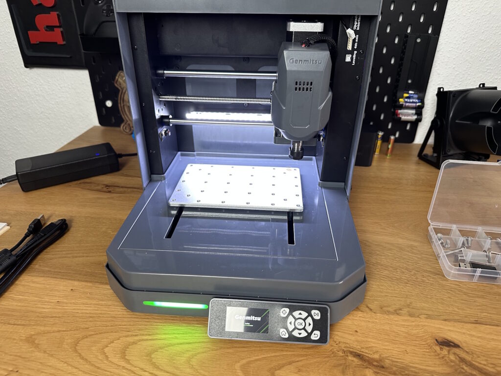
The Cubiko is designed to make CNC accessible to everyone. Its exterior design already promises a far more inviting character compared to the open DIY design of, for example, 3018 CNC routers. An enclosed build chamber is not only safer in case a cutter breaks (which will definitely happen for beginners), but it also dampens noise, allowing the Cubiko to be used on a desk. However, the machine is still not exactly quiet. Primarily made of plastic, the Cubiko features an emergency stop button, an on/off switch, a USB interface for PC control, and a barrel connector for the power supply on the right side. There are no additional ports. On the back, a rubber stopper is installed, which serves as a pass-through for the air compressor hose when using the laser module.
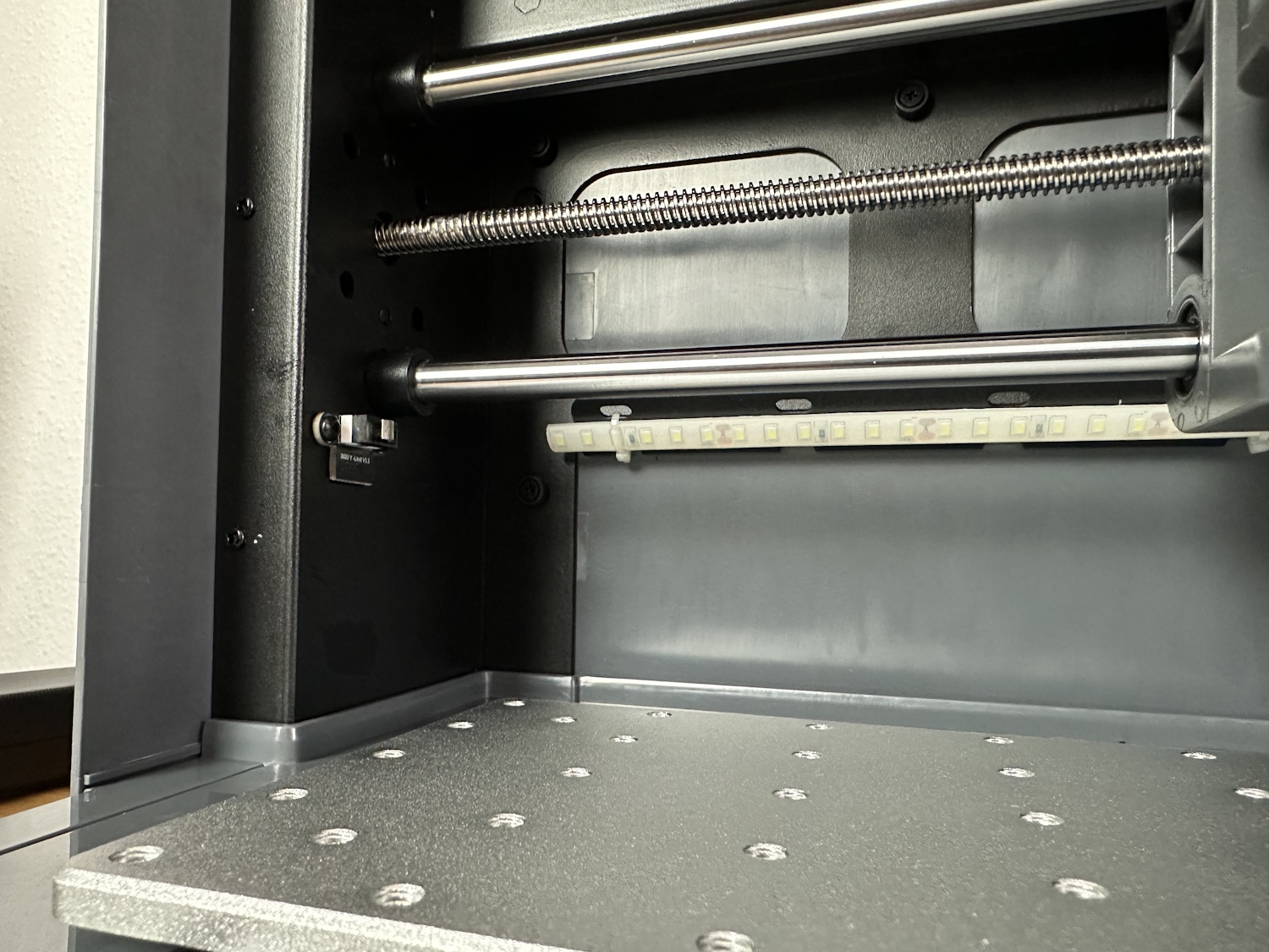
Inside, the machine makes the entry for beginners significantly easier with small features that are not always included in other entry-level machines. Not only are limit switches installed on both sides of all axes, but an LED strip on the back provides proper workspace lighting through the slightly tinted protective shield, whose correct installation is also monitored by a contact switch. Without the cover, the machine will not start its motor, and if the cover is opened during milling, the program pauses, and the motor stops. This should absolutely be avoided, as when the cover is reattached, the motion system starts immediately, but the motor has little time to reach its speed—leading to quick cutter breakage.
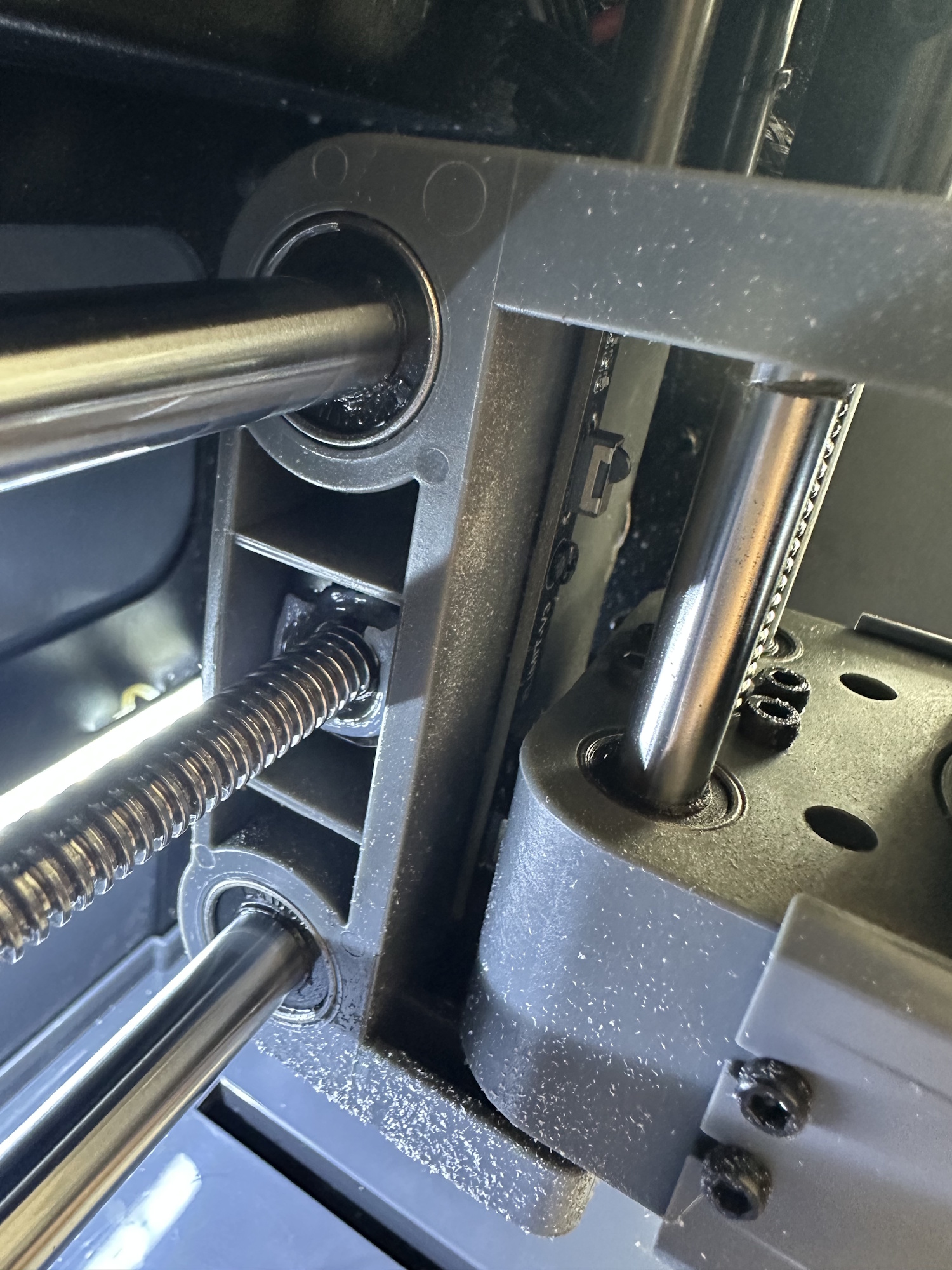
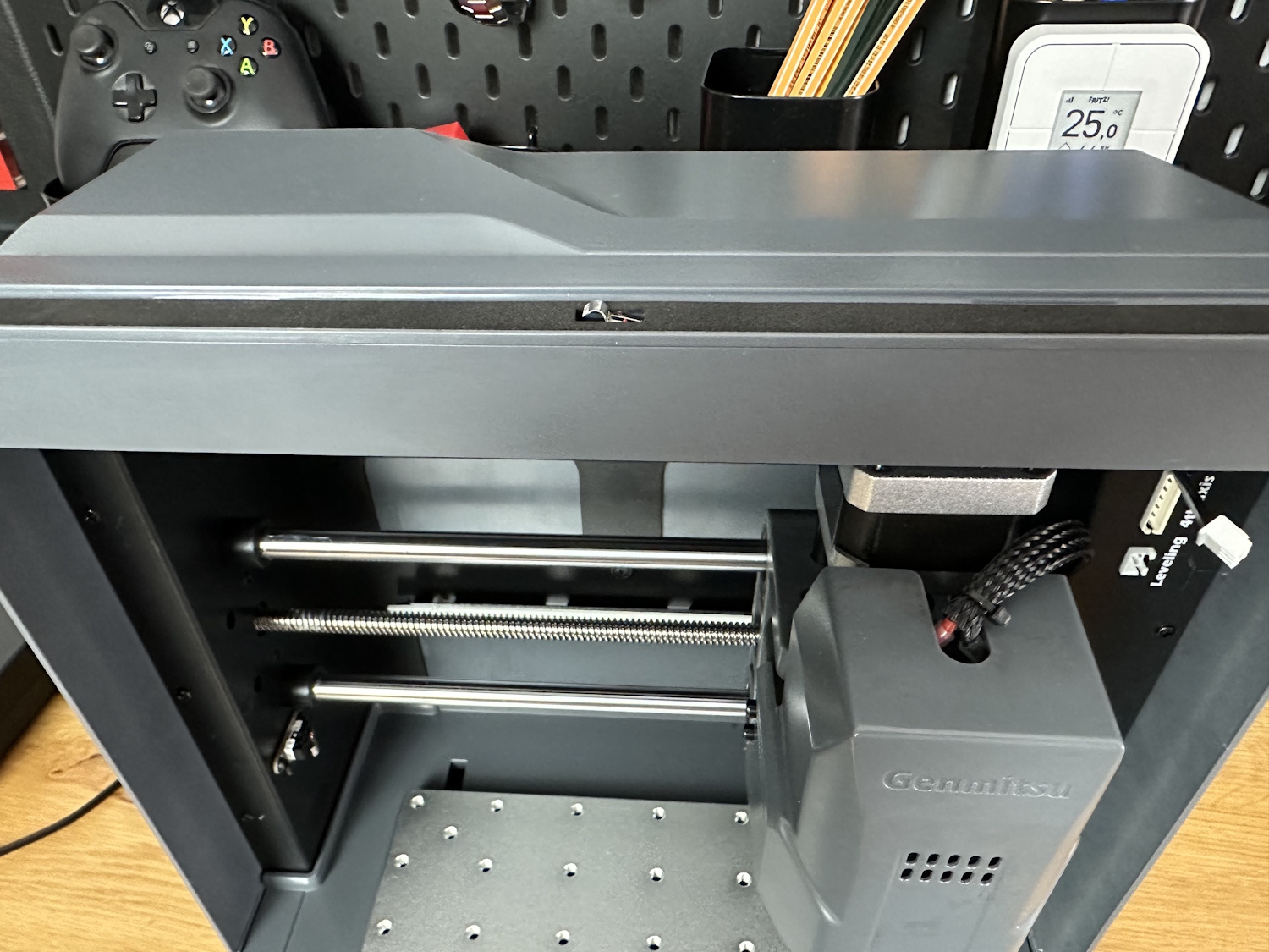
Overall, the Cubiko makes a good impression. Everything is cleanly finished, all cables are hidden, and even the motor has a cover. While temperatures rise under the hood, I haven’t observed critical temperatures during longer projects so far—only a long-term test will show whether this leads to premature motor wear or remains within acceptable limits. However, the noise reduction is a significant advantage. The stiffer construction also results in fewer vibrations, further reducing the noise level compared to a 3018.
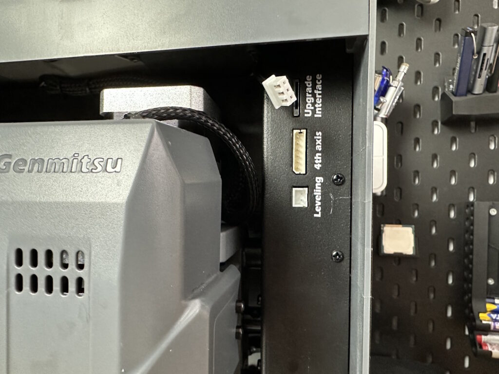
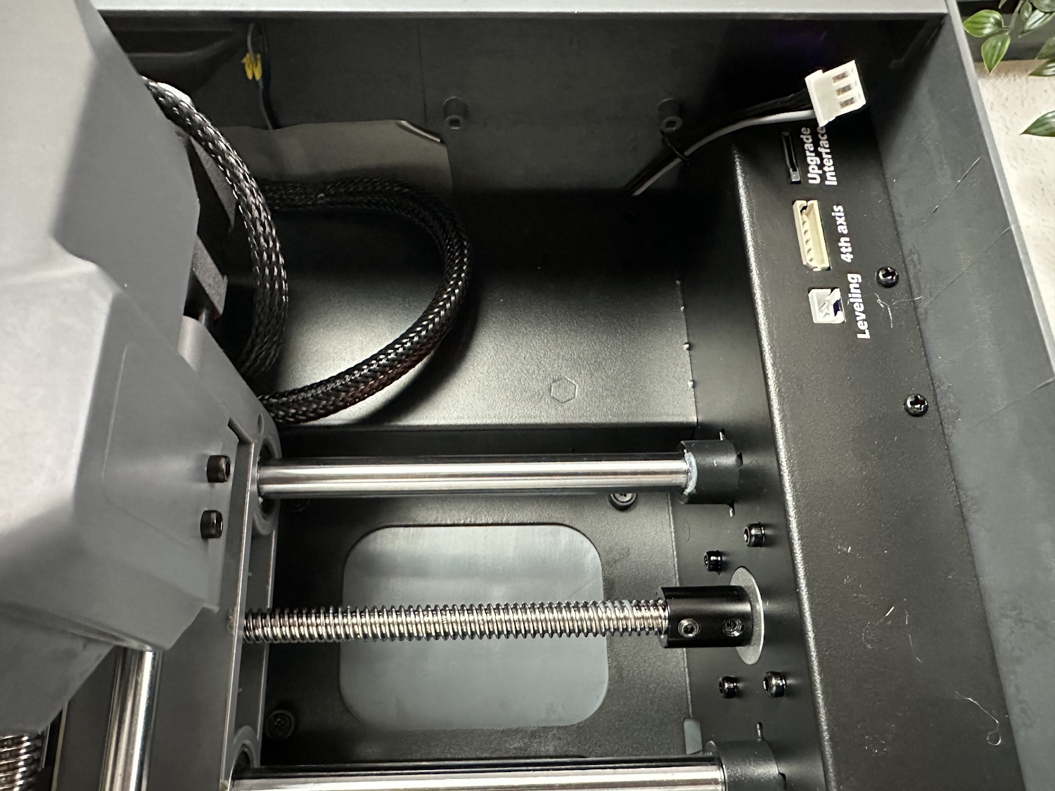
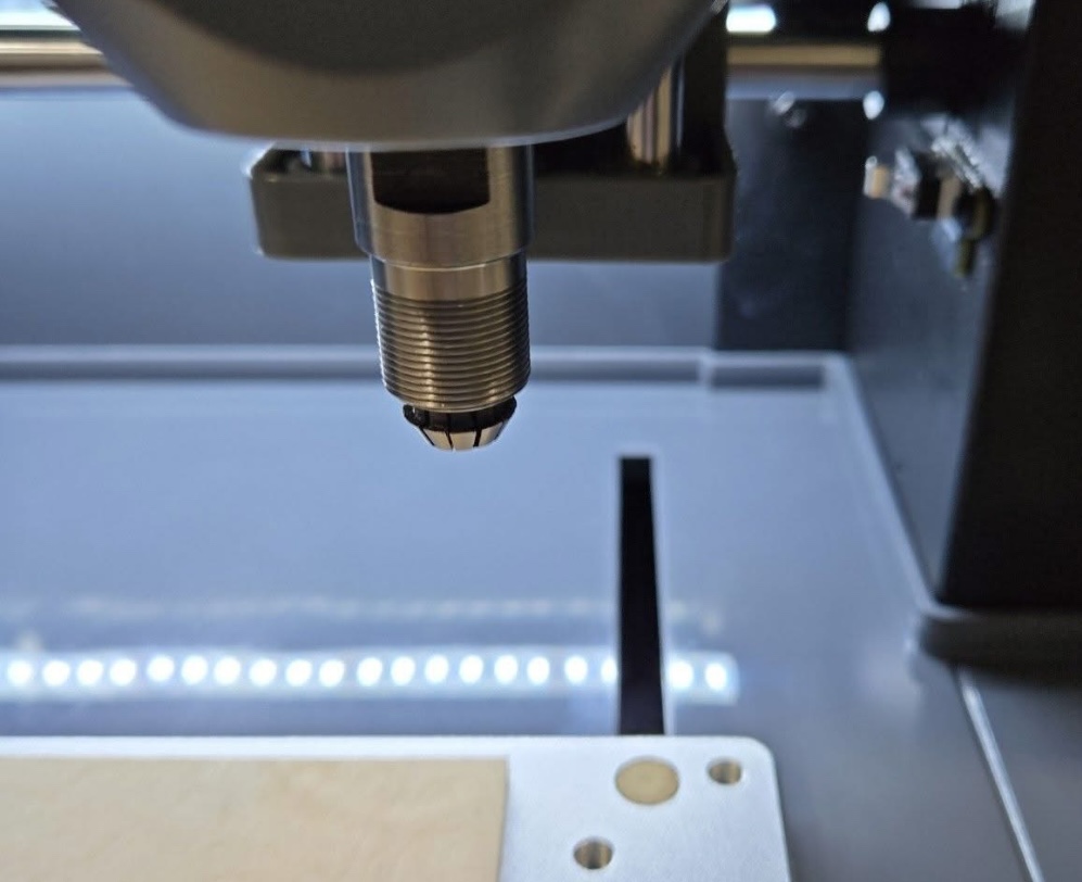
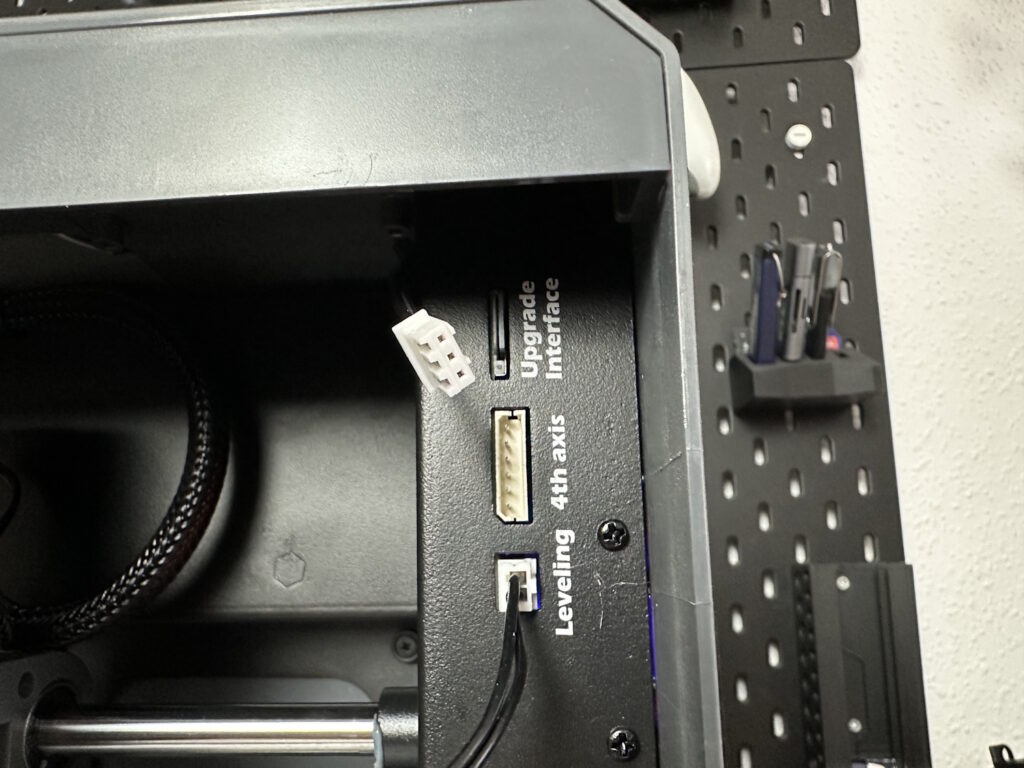
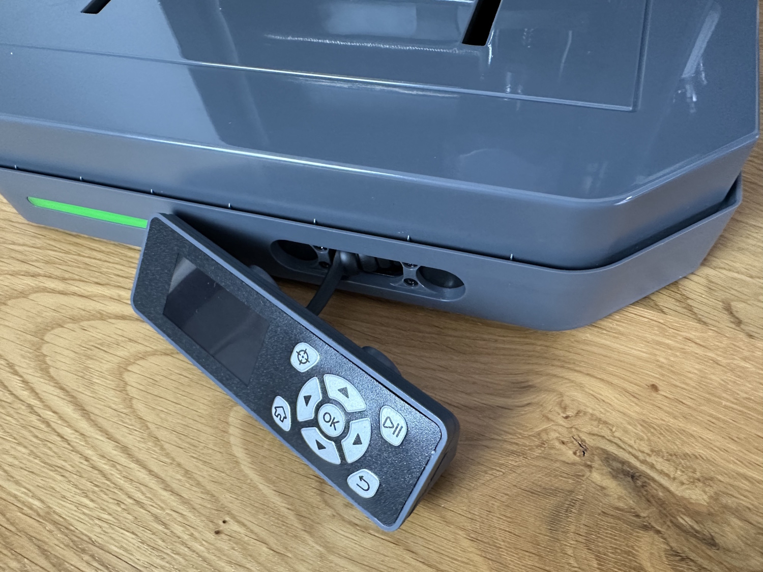
The white connector prominently visible in the image is for the optional laser module. This is available for approximately €100 in the SainSmart shop as an add-on. Additionally, a rotary module, a fourth axis, a pen holder, and later possibly a polishing attachment are offered. The lowest connector is used for calibrating the tool sensor or creating height profiles. A small cable harness with an alligator clip and a spade connector is plugged in there as needed.
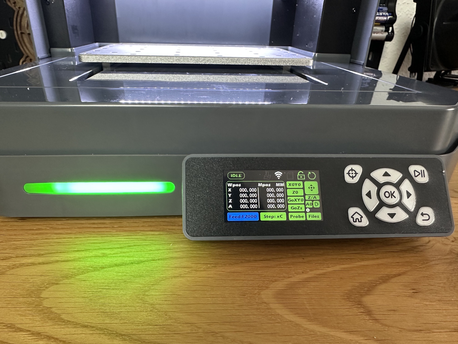
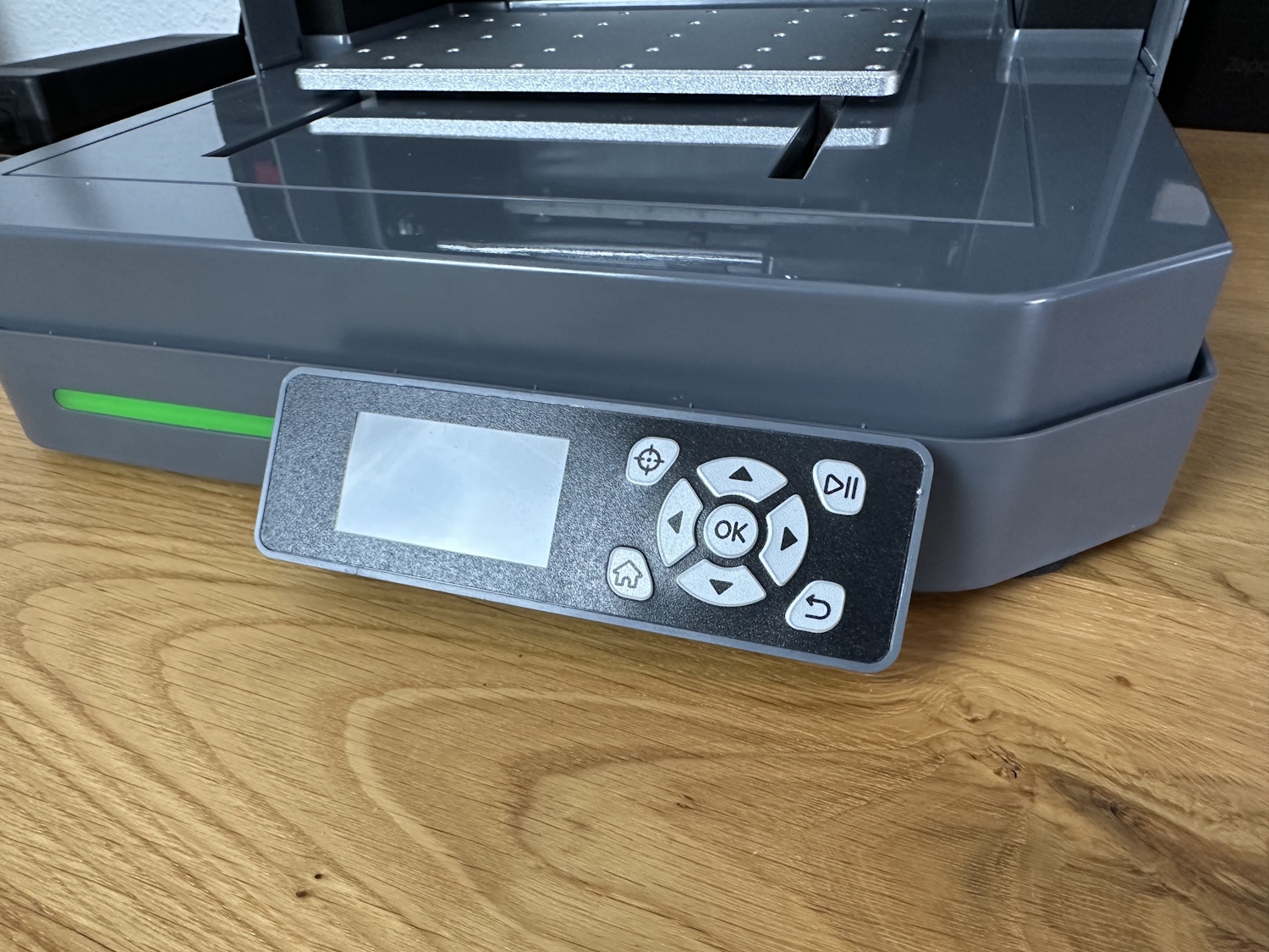
However, the display and control unit feel somewhat outdated. The display is sharp enough to read everything, but it could have been a bit larger. The buttons are not actual buttons but rather a plastic film, likely placed over simple microswitches. Functional, yes, but nothing more or less.
Setup
For setup, only the four foam feet needed to be attached to the Cubiko, as the machine is delivered fully assembled. Oddly enough, as reported by me and others in the corresponding Kickstarter backer group, the collet was stuck in the motor holder instead of the collet nut, which caused confusion for some users. In fact, the collet can only hold a bit when properly installed. This could be fixed with pliers, though a screwdriver can also help.
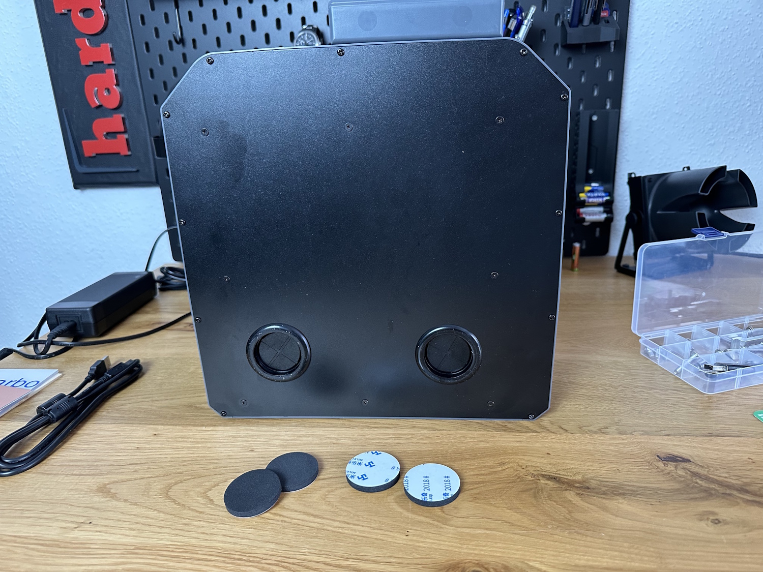
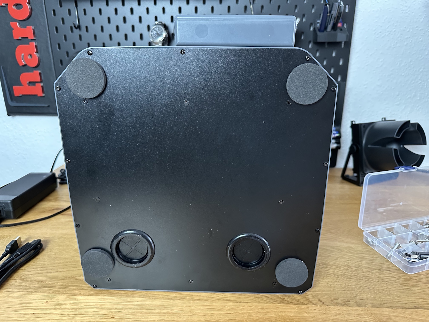
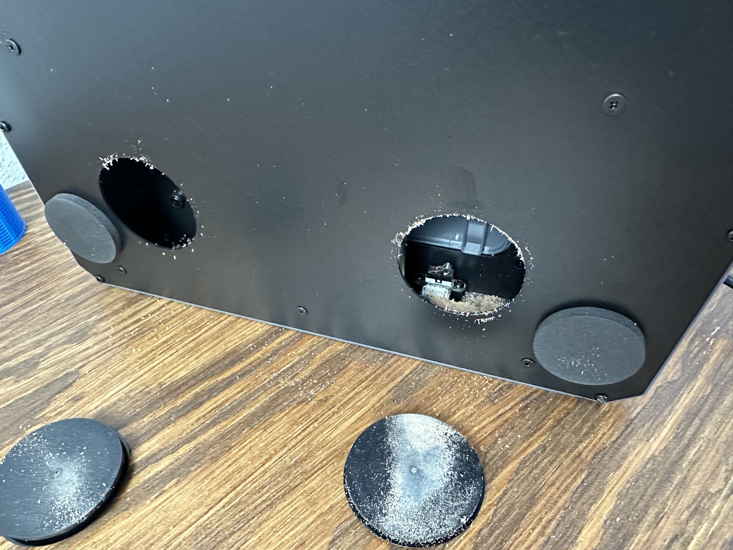
The large rubber stoppers provide access to the interior for cleaning. However, not much debris falls inside through the narrow slits—only a small amount accumulated after producing all the test parts shown in this article (without using a dust collection system).
After completing the setup, I always flash the latest available firmware, which can be done via the SD card slot built into the offline controller. The firmware can be downloaded directly from SainSmart. Especially with newly released products, issues often arise, and the Cubiko is no exception. Before the update, the app connection repeatedly displayed messages indicating that the emergency stop was pressed, the Wi-Fi module was not installed, or no SD card was present, even though one was inserted in the controller. These three issues were resolved after updating to version 43.
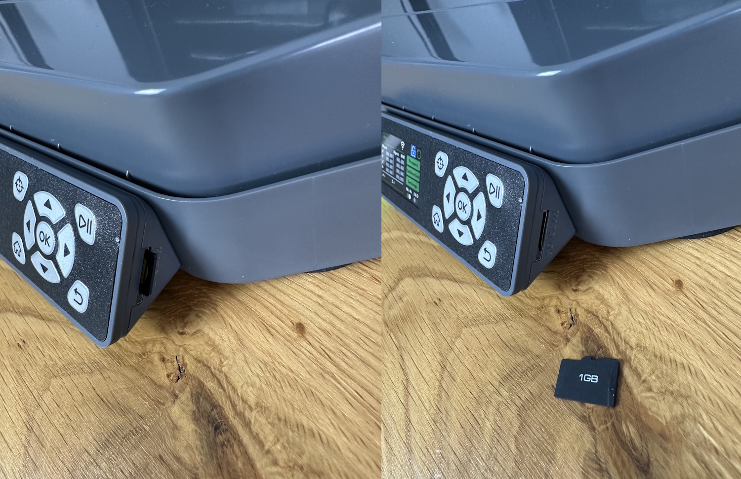
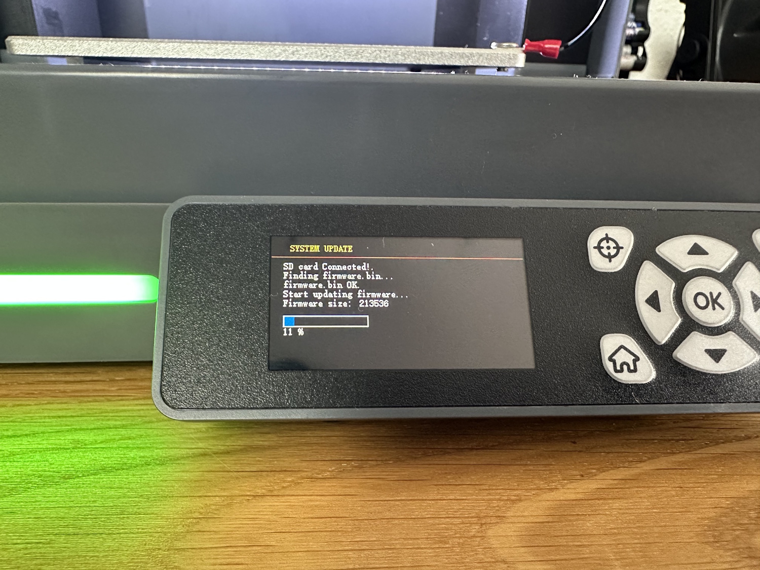
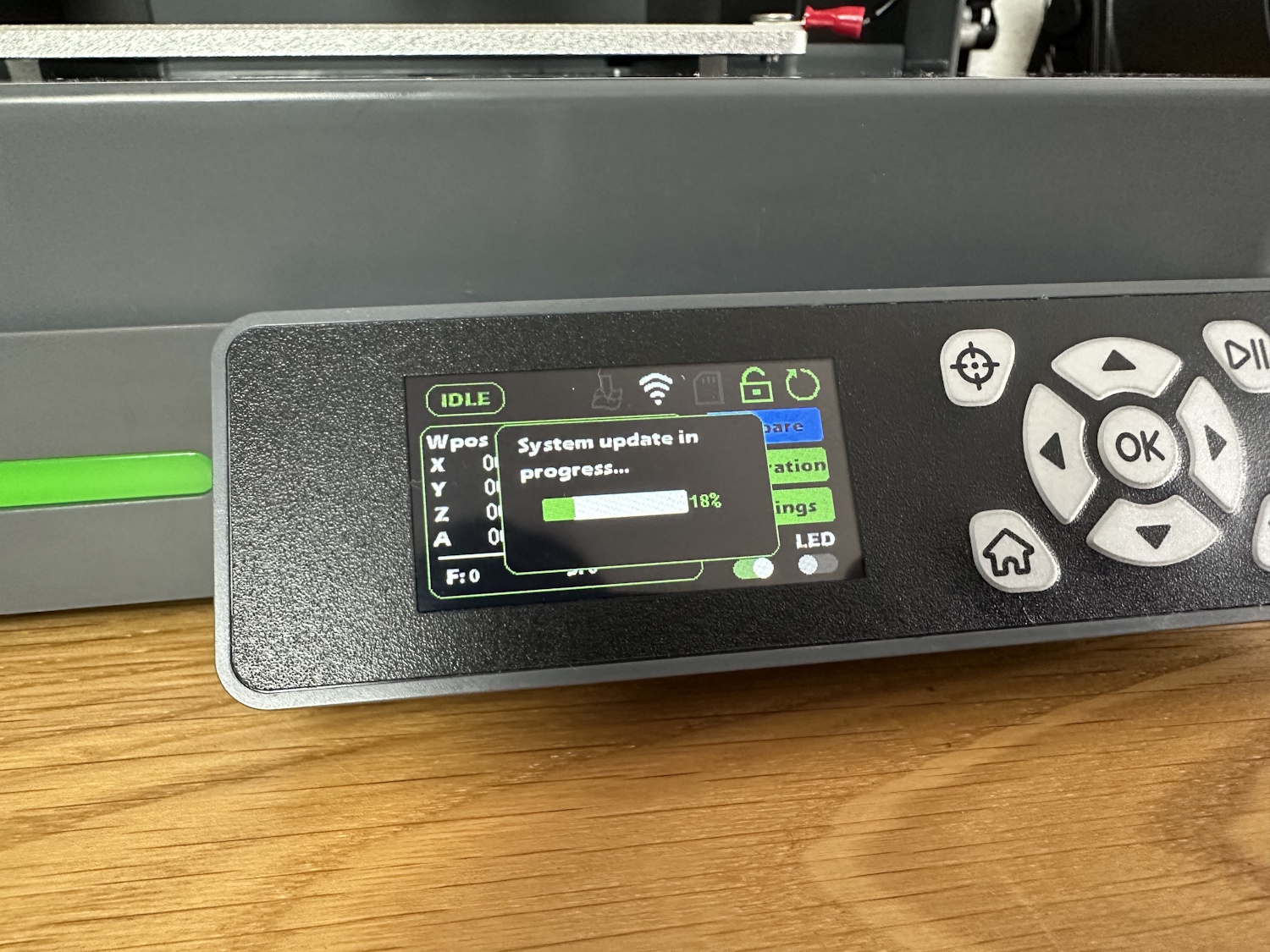
The raw firmware.bin file simply needs to be copied to the root directory of the SD card. After inserting the SD card into the controller and starting the router, the new firmware is automatically installed. The middle image shows the upgrade process via the SD card slot on the display, and the right image shows it via the “Upgrade Interface.” In fact, the process is somewhat poorly described on the SainSmart website, especially since new firmware was released during the creation of this article. The test was mainly conducted with version 43.1, where at least the folders for the firmware file had appropriate names, as the router itself also has an SD card slot on top.
“Upgrade Interface” – with firmware version 44, the file names consist only of Chinese characters. The translation revealed “control board” for one file and “mainboard” for the other. This doesn’t provide much clarity, especially since additional firmware can be loaded via the app when connected to the router. I suspect the router’s microcontroller has its own firmware, and the Wi-Fi module has another… but we’ll dive into app control in more detail later. When trying to check the changelog, I noticed the specified values didn’t match, so I reloaded the firmware. It turns out I likely used the file for the wrong module and temporarily bricked the display. Fortunately, the CNC wasn’t permanently damaged, so I could simply flash the correct firmware again. This shouldn’t be necessary—SainSmart, please improve the documentation. Oddly, before correcting this, the spindle motor started immediately after powering on, which isn’t exactly safe. This issue also occurred to other users in the Facebook community during our test period. It’s unclear whether flashing both firmwares is necessary or if one method is sufficient, as well as what the app-based firmware update actually does.
Once everything is functioning and updated to the latest version, it’s time to calibrate. It’s checked whether an assumed 100 mm movement in the X+ direction actually corresponds to 100 mm. Theoretically, you could start without these steps, but investing some time here improves all projects created with the Cubiko. We explained this step in detail in the 3020 test, which you can find here. For the Cubiko, the deviation was 0.2 mm in X and Y (over 50 mm) and 0.2 mm in Z, which is likely sufficient for most projects out of the box, but this can be quickly reduced to under 0.09 mm.
The bed and its inaccuracies can be directly checked with the Z-probe function, resulting in the following values:
| -0.018 | -0.042 | -0.281 |
| -0.059 | 0 | -0.223 |
| -0.043 | 0.025 | -0.157 |
The table represents the bed as viewed from above. Assuming the center measurement is 0, the deviations at the other measurement points are shown. The bed at the position of the integrated probe in our unit is almost 0.3 mm lower. For normal milling tasks, this automatically leads to inaccuracies. For PCB production, the height profile feature should always be used, where the PCB is re-measured in Z to eliminate such inaccuracies. For woodworking, 0.3 mm should be negligible. As with our other tests, such as the 3020 PRO Max, creating a sacrificial wooden board processed directly by the router further reduces inaccuracies. The other values, averaging half a tenth of a millimeter, are perfect.
Using a dial gauge, I checked the backlash, i.e., the play between forward and backward movements of the individual axes, and obtained the following values:
| Cubiko | Cubiko Load | 3020 PRO MAX | 3020 PRO MAX Load | 3018 PRO DIY | 3018 PRO DIY Load | |
| X | 0.04 mm | 0.2 mm | 0.02 mm | 0.15 mm | 0.1 mm | 0.4 mm |
| Y | 0.07 mm | 0.3 mm | 0.1 mm | 0.25 mm | 0.1 mm | 0.4 mm |
| Z | 0.08 mm | 0.7 mm | 0.02 mm | 0.2 mm | 0.1 mm | 0.4 mm |
The load values attempt to show the play when manually applying some pressure to the spindle in the respective axis. This is more for comparison and will behave differently during milling, as the stepper motors actively stabilize the head in a given direction. However, it provides some insight into the rigidity compared to the other two machines.
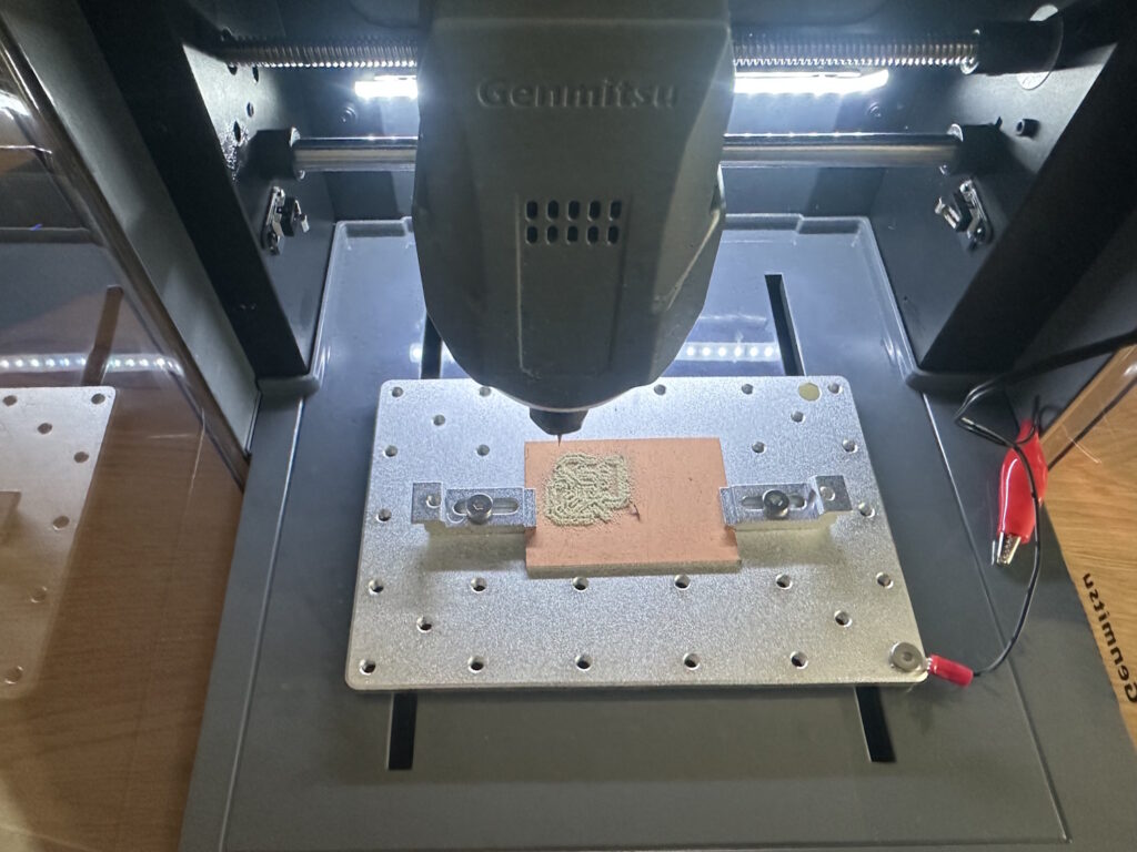
Before starting, the tool sensor is calibrated again. Using the display, select Calibration and Z Probe, or with the latest firmware, “Plat Calibrate” (likely meant to be Platform Calibrate, but SainSmart needs to revisit the firmware). SainSmart explains this step-by-step on their website. Using the included cable harness, alligator clip, and spade connector, a circuit is created between the cutter and the bed. The Cubiko moves to the tool sensor at the back right (golden circle) and measures when it triggers. Then, it moves to the bed height and checks when the circuit is closed via the bed. This deviation (the tool sensor is lower) is stored in the GRBL settings, allowing all tool lengths to be automatically probed without always connecting a cable to the cutter and moving down to the material. However, with this method, the material thickness must be precisely measured and specified (Start Z on the workpiece surface), or Z 0 must be set to the machine table in the CAM program—depending on your preference.
Control
Overall, the Cubiko can be controlled in three different ways: via the front controller, a Wi-Fi app, or USB in combination with a PC. All standard functions can be accessed with all methods, though for app and USB control, macros must first be created to ensure the tool sensor works correctly. This means the machine retrieves its position via a homing cycle, moves to the sensor, and subtracts the correct offset from the measurement. This is supposed to be simplified in the app soon—we’re looking forward to the next update. The heightmap feature can only be used via the integrated controller.
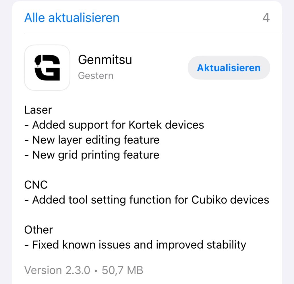
Update 08/23/2025: The Genmitsu App 2.3.0 now supports the tool sensor:
Offline Control
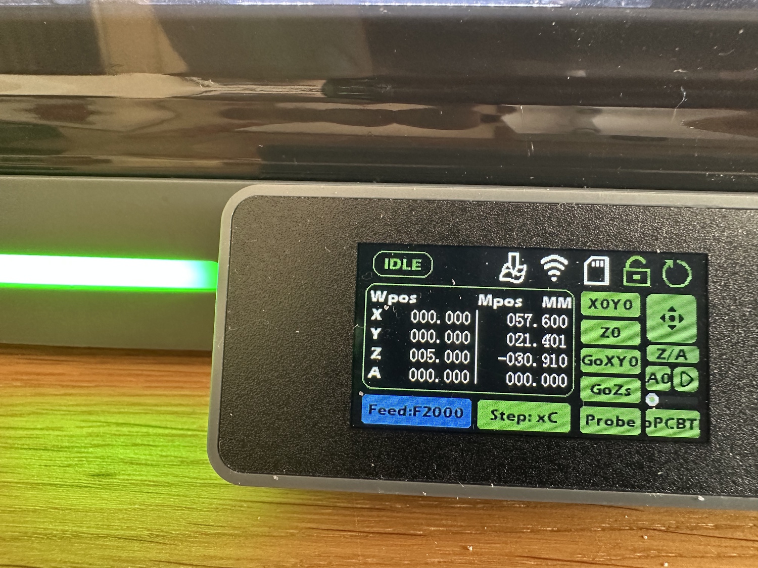
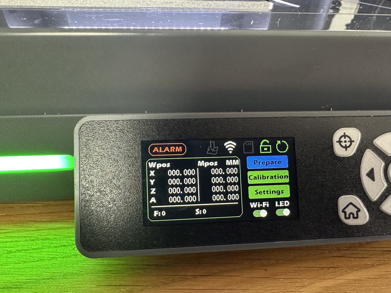
The control unit on the front is also referred to as offline control, as it can access all router functions offline without additional devices and process projects loaded via an SD card. The manual explains with images and descriptions which button is intended for which function and how a typical workflow looks. Almost all subsequent projects could be created this way. However, it takes some getting used to, and navigating the menu solely with up and down arrows can be tedious, especially when you want to adjust the step size from the second-to-last menu item and have to press up 10 times instead of once to the left. Similarly, for height adjustment, it’s not as simple as pressing OK for the menu and then using up and down arrows as you might expect—no, you need to move the cursor to Z and then press left for down and right for up, which is almost self-explanatory. The normal movement menu for X and Y, just above, is activated with OK, and the arrows correspond to the respective directional movement as depicted.
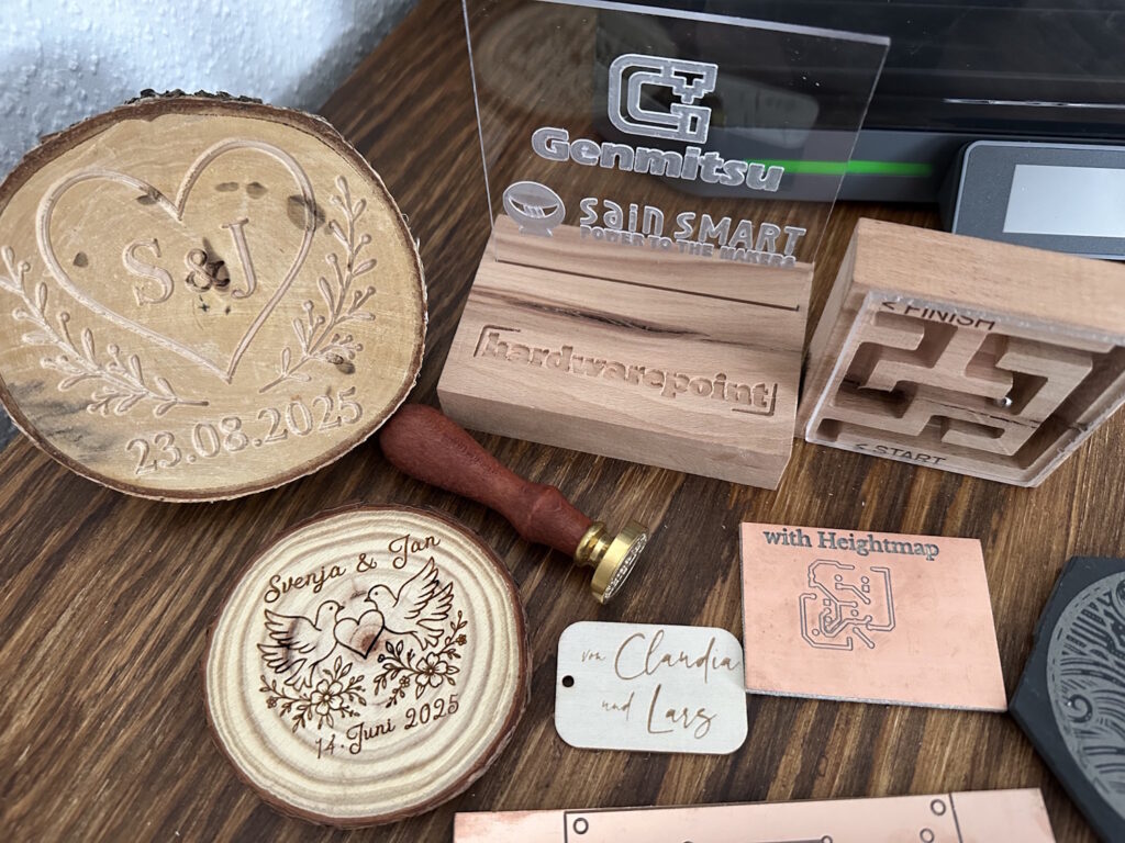
Before we really dive in, here's a sneak peek of projects created on the Cubiko. The lasered items are for example only, as we did not have the 5.5W laser module for testing – however, these projects can be made with exactly such a module. All other projects were made directly on the Cubiko with the included bits. Only the maze also had a normal 1/8" end mill for support.
What's Next?
Want to see more about what the Cubiko can do? Check out our next article, where we dive into advanced projects and detailed features of this versatile CNC machine!


