Written by Graham
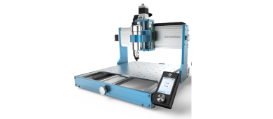
This is a guide as to how to set PROVerXL 6050 Plus up. It covers some tests, optimizing some Grbl settings, making, surfacing, and engraving a Spoilboard, and mounting a Laser.
Full designs and Gcode files for the Spoilboard are included.
For my assembly hints and tips please see my review Even if you have already assembled the router there are parts that are worth reading.
Join our CNC user group: https://www.facebook.com/groups/SainSmart.GenmitsuCNC/permalink/3227105410933604
The main target audience here is novices, if some parts seem a little long-winded to you then just skip the details.
I am using Candle as the Gcode sender and control program for all examples and details, others are available, which one you use is a matter of personal preference.
Saving the Grbl Settings
The first thing I always do is make a backup copy of the Grbl settings, also after making any long term changes I always make another backup just in case.
In the Candle console pane send a $$ command, it will respond with a list of all the current Grbl $= settings. Copy these and paste into a text editor and save the file somewhere (6050 Original Settings.txt is a good file name).
Control box
There are a number of buttons, knobs etc on the control box, this is a brief description of them. These affect the way the router works, or doesn’t work!

Mains Voltage selector
Located on the left side of the control box this red slider switch selects the mains input voltage to the router, two positions one for 110V, one for 240V. Before connecting to the mains it is VERY important that this is set to the correct mains voltage.
Power on/off
Located at the rear of the control box the mains power has an on/off rocker switch at the rear of the control box.
NOTE: Just connecting a USB cable can provide sufficient power to turn on some internal LED’s and power the control board. BUT if the mains power is not connected and turned on then the Front Green Switch LEDs will not light and the Stepper motors, spindle motor or Laser will not function.
The rest of the controls are located on the front of the Control box. From left to right:
Laser/Spindle Motor
Push switch, in is Laser mode, out is Spindle mode. All this switch does is that when depressed the Spindle motor power is turned off, it will not set the Grbl Laser mode or other settings, it does not affect the operation of the Laser which will function with the switch in or out.
Speed
A potentiometer to control the power going to the Spindle motor and so it’s speed. This is the only way to control the Spindle Speed, the Gcode commands will turn the spindle on and off but will NOT control the spindle speed. The operation of this is NOT linear, if max is 12,000 RPM then hallway will not be 6,000 RPM.
Reset
A momentary press switch, pressing this will reset the controller, the same as sending a reset command from the Gcode sender. Everything will stop, no resume is possible if this is pressed during a job.
Pause and Resume
These are Momentary press switches. Pressing Pause executes a feed hold, all the steppers will stop moving the axes and processing the Gcode will stop. Pressing Resume will restart everything.
NOTE: This just pauses and resumes movement on the XYZ Axes, if turning the Spindle will NOT stop, if using a Laser it WILL CONTINUE to burn!
Stop
An Emergency Stop, everything will stop. If turning the Spindle motor will stop, if burning a Laser will be turned off.
It is not possible to resume after this switch has been used as the router will lose its position and reset.
This is a latching switch, once pressed it locks down and can only be released by twisting the button in the direction of the arrows. This being accidentally pressed and still being locked down is a common answer to ‘Why doesn’t my router work?’
Simple tests
Once it is assembled there are some simple tests which are worth while performing. These apply to most similar routers regardless of the manufacturer or model. They are pretty basic and are designed to detect any assembly errors and possible errors with cabling. It is very rare but always possible that there is an error in a cable somewhere, in my case it’s more likely that I forgot to plug one in!
Install Candle according to the User Manual, start Candle, connect the USB cable and turn the router on, (the order does not matter, but if the router is not powered on the axes will not move!)
Limit Switches
Just to make sure they all work unlock the router, then trigger a limit switch manually. The router will return an Alarm 1 error in the console pane. If it does not then there is a problem with the limit switch or more likely the wiring, check all the connections. It is much better to find out one does not work triggering it by hand rather than having the stepper motors trying to force the router past one.
Reset the router, unlock and trigger the next switch. Repeat until all 6 switches have been tested and are working.
Movement
Either manually or using the jog controls move each axis along its full travel. It should move freely without any signs of binding, preferably by hand as then you can feel any changes in resistance if there is binding. If an axis starts to bind using jogging one sign is that the ‘note’ the stepper motor makes will change but this is not guaranteed.
If you hit a limit switch just reset, unlock, move away from the triggered switch and continue on the next axis.
Basic Calibration
Simply check that if you tell an axis to move by 100mm (for example) it does actually move 100mm. It is very unlikely that this will be a problem but it is worth checking.
On the X and Y axis place a ruler along each axis in turn, position the router at Zero (use a V bit close to, but not touching, the ruler for accuracy) and jog 100mm. If the router does not move 100mm there is a problem.
Repeat for the Z axis, but try 50mm of movement. Measuring this is more difficult on the vertical.
If the measurements are out then check the router settings and think about calibrating the axis, but that requires a lot more effort than just measuring along a ruler once.
Spindle Motor
When started the motor should turn in a clockwise direction, if it turns anti-clockwise then the wire connections to the motor are probably reversed. Set the Speed potentiometer to a low setting and from Candle start the spindle, check which direction it starts rotating.
Homing
Run a homing cycle, by default the router should go to the top, back, right position and then back off from the limit switches so they are no longer triggered and be ready to use. Z is homed first, then the XY axes.
Coordinate Systems
Just a quick note, a Grbl router has two sets of coordinates for any position, the Machine coordinates and the Work Coordinates. The Machine coordinate origin is set by Homing the router, the Work Coordinate origin by setting the X Y and Z zero positions at the desired point. All Gcode will use the work coordinate origin as a starting point and through the job. Machine coordinates can sometimes be useful though for things like moving to a specific point. For Both systems:
- The X axis is -ve to the left and +ve to the right of the origin.
- The Y axis is -ve to the front and +ve to the back of the origin.
- The Z axis is -ve down and +ve up from the origin.
For relative movements X-5 means 5mm to the left, Z2 means 2mm Up…..
As Homing will pull back a little after triggering, the post homing machine coordinates will be -3, or whatever the Pull off distance is set to. See Limits and homing control ($20-27) for more detail
If you don’t run a homing cycle the machine coordinates are zero wherever the router happened to be when you turned it on. Not recommended!
Measuring maximum travel or Cutting area.
I like to measure the available movement on each axis accurately. It can be useful to know by displaying the Grbl settings what the actual maximum travel values are and it is also needed to use soft limits or position a spoilboard accurately.
NOTE: I have already set the homing pull off value $27 from the default of 3mm to 1mm.
From the home position note the machine coordinates for the axis in my case -1 -1 -1, then jog each axis in turn until the limit switch is triggered at the other end of the axis. The difference between the start and end machine coordinates is the maximum travel on that axis.
These values are stored in the Grbl $130-132 values for the X, Y and Z axes. I do suggest knocking off ~0.5mm from each value to ensure that the limit switches are not triggered accidentally by going too close to the edge.
- On my X axis, after homing to the back right my X machine coordinate is -1.
- Jogging left until it triggers a limit switch, at the triggering point my X machine coordinate is -606.35.
- The difference is 605.35 so knock off a bit for safety leaving 605mm.
My cutting area measures 605 x 500 x 126mm (23.82 x 19.69 x 4.96”)
Increasing the Maximum travel
There is some unused travel which may be available on each of the axes with some modifications to the limit switch stops. On the X axis I would estimate there is an extra 15mm of travel at each end by modifying the end stops. But the left hand end stop is also the X Drag chain mount so it’s not that simple.
On the Y axis I estimate there is another 5-10mm available at each end by modifying the end stops and/or limit switch mountings. But the travel is already very close to the front of the bed, depending on which motor is mounted.
On the Z axis there is another 3-4mm of travel available both top and bottom. This can partly be achieved by just bending the Stop tabs out a little.
With all modifications (NOTE: I have not made all these modifications so these are just estimates) my cutting area would possibly increase to 633 x 516 x 130mm (24.9 x 20.3 x 5”)
I currently have this down as not worth the effort as the increases are very small (~4%), it’s big already and really if you need the extra few mm look at a bigger router. The Z axis travel already exceeds the maximum stock height, but I did inadvertantly modify the end stops by failing to plug the Z axis limit switches in firmly! As this method involves lots of grinding noises I do not recommend it!
GRBL Settings
Grbl has a lot of settings which control its operation, the values for some of these are personal preferences but I think they make sense. NOTE: ALL settings use the metric system! It doesn’t matter if you are using inches or not ALL settings use mm, mm/min or mm/sec2 for accelerations.
Each setting has a number, a setting is changed by sending a $nn=Val command to the router where nn is the setting number and Val is the new value. The new value will be saved on the router until it is changed.
The current settings can be displayed by sending a $$ command, this will return a list of all the setting numbers and their current values.
Stepper motor lock and Pulse ($1)
$1 controls the time in ms after which the steppers will be unlocked when stopped. A Locked stepper tries to stay in the same place and resists movement. If set to 255 they will be permanently locked as long as the power is on.
If you are performing tool changes then keeping the steppers locked will help prevent inadvertent movement, the downside is that using the manual knobs to move an axis should never be attempted with the power on and the power consumption (minimal) of the steppers will not fall when idle.
Report in inches ($13)
Grbl operates in mm, if you set the movement units to inches in Grbl then the first thing the control board does is convert them to mm. By default ($13=0) any position reports it sends back are in mm. However you can tell it to report in inches by the $13 setting. This should mean that your Gcode Sender will display things like coordinate positions in inches rather than mm. If you habitually use inches try setting $13=1.
This does not affect any units set and used in a Gcode file or other commands, just the units Grbl will report in. As I use mm I have not fully tested this.
Limits and homing control ($20-27)
There are two types of limits used to prevent the router from trying to move out of the cutting area, hard and soft, both these limits prevent the nasty grinding noises as the stepper motor tries to force an axis past its limit of movement. You can use one or both or none, however limits can only be used if a homing cycle has been run setting the machine position accurately.
Soft limits ($20)
Set to zero they are disabled, set to 1 they are enabled.
When enabled each movement command is checked before it is executed, if it would result in the router moving past the maximum travel limits ($130-132) from the machine home position on each axis the router stops before the command is executed.
To use soft limits effectively the maximum travel distances ($130-132) must be set accurately.
There can be some problems using soft limits, mainly when using a Z-probe, the Z Probe commands include a ‘how far should I travel before I encounter the probe’ distance, this depends on the position at the start of the probing command, if the maximum would exceed the machine limits an error will be reported.
Hard Limits ($21)
Set to zero they are disabled, set to 1 they are enabled.
Quite simple, when the router triggers a limit switch at the end of any axis it will stop. The machine and work position will then be inaccurate as there may have been instructed movement which has not completed. I cannot see a reason to turn these off.
Homing ($22-27)
By default homing is enabled ($22=1) to disable it set $22=0. Homing must be enabled and a homing cycle must have been run to use Soft limits. Grbl will generate an alarm at startup if enabled until a homing cycle has been run.
Homing is started by sending a $H command to the router, all Gcode senders will have a button to do this automatically.
The homing process is:
- Move from the current position towards the corner set by $23 at the homing seek rate set by $25. The Z axis is homed first.
- When a limit switch triggers:
- Back away a little to clear the limit switch
- Re-approach the switch at the slower Homing feed rate ($24) until the switch is triggered again, the slower approach should give a more accurate reading of the position than a high speed crash.
- Back off by the Homing pull-off $27.
- Note: Some GRBL boards will record the zero position at the point the switch was triggered, some will record the zero position at the point after the homing pull off distance. The 6050 records it when the switch is triggered so after the pull off so the coordinates will all be the $27 pull off distance.
- If there is an error such as a limit switch cannot be found or the pull off failed to un-trigger a switch an alarm condition will be raised and Homing will fail.
Homing Direction Invert Mask ($23), Where does it home to?
You can select where (which corner) the router home position is. This is controlled by the Homing Direction invert ($23) it takes a value of 0-7 which indicates the corner as shown. $23=0, the default setting, specifies the Back Right Top. To change the corner change the $23 value. I strongly suggest that only the top corners (0-3) are used to keep the bit away from clamps, stock and the bed.

Homing Feed ($24)
Increase to reduce the homing cycle time but this is only going to apply when the axis is already very close to the limit switch so it’s not going to make much difference. Mine left at the default.
Homing Seek ($25)
Increase to reduce the homing cycle time but remember that the seek phase will end on each axis by crashing into the limit switch at full speed. Too fast and you will potentially cause damage over repeated homing cycles. Mine left at the default.
Homing debounce ($26)
When a mechanical switch is triggered the contacts can bounce on and off for a short time while it settles down. The debounce is the time in ms to wait to let the switch to settle down before reading it again. Makes virtually no difference to the speed of the homing cycle, however 50ms should be sufficient for any debounce interval so mine is set to 50ms.
Homing Pull Off ($27)
After a limit switch is triggered during homing the router will pull back from the switch by the distance set in $27 to ‘un-trigger’ the switch. By default this is 3mm but this can be reduced, I use 1mm.
Spindle motor/Laser power settings ($30-32)
Grbl holds the maximum and minimum rotation speeds for the spindle, $30 and $31. These are also used for laser power when a laser is connected.
The spindle speed on the 6050 is controlled by the potentiometer on the control box, when using a spindle motor, apart from commands that will start or stop the spindle, any Sxxx commands and any relevant settings values are ignored. When the motor is started it will run it at the speed set by the potentiometer, anything that will stop it will set the speed to zero.
The $30 and $31 Max and Min values can be ignored for a spindle motor and can be left set to Laser values. Laser power is controlled by the Gcode, not the potentiometer.
Spindle/Laser Max ($30)
For a Laser the power is controlled by a PWM signal, a value from 0 to 255, or 256 possible values. For a Laser I change this to 1000, personal preference. This must match the Maximum power setting in your laser software!
Spindle/Laser Min ($31)
The minimum power ($31) default is zero so that is left as is. This should match the Minimum power setting in your laser software!
Laser Mode ($32)
Tells Grbl if you are using a Spindle Motor ($32=0) or a Laser ($32=1). This needs setting correctly when you switch between them. Note: This is not changed by the Laser/Spindle button on the control box.
Steps per mm ($100-102)
A stepper motor will only turn by a certain angle each time, this is a step. The number of steps per mm will not only depend on the stepper motor but also on the gearing used (leadscrew) on the axis.
Only change these if they are corrupted or after performing an accurate calibration of the axis. Mine left at the default.
Max Rate ($110-112)
For each axis the maximum rate it can be moved in mm/min. If Grbl sees a requested Feed rate (Fxxx) that exceeds the value for an axis then this value will be used instead to prevent the router from overloading and missing steps.
This does not mean the router can make a cut at this rate, just that it can move without any load at this speed.
This would need a set of tests to change the speeds reliably so for now mine are left at the default.
Acceleration ($120-122)
To move anything you need acceleration, going from rest to 2,000 mm/min instantaneously is physically impossible it’s all about momentum. Think of a high powered sports car, put your foot down and it may accelerate rapidly but will not go immediately to 100mph.
Grbl uses these values to determine how fast it can speed up and slow down the movement to achieve a movement rate. The maximums depend not only on the router but also on the mass of the spindle motor. Put on a 200g Laser and you will be able to accelerate faster, change that for a 2kg spindle motor and it’s going to be slower.
Faster accelerations will reduce machining times, and if using a laser it can help to reduce overburn at the corners. Set them too high and the router will be overwhelmed, miss steps and your work will be ruined. For now I am leaving these at the defaults until I can run some comprehensive tests.
Maximum Travel ($130-132)
Used by Soft Limits, (also for the maximum travel distances during homing with a 1.5 multiplier) These are the maximum distances in mm each axis can safely move (No sign, if an axis moves from 0 to -100 or 0 to 100 the travel is 100). I have set the XYZ values to my measured movement distances on the XYZ axes which are $130=605, $131=500, $132=126.
Other Settings
Some of the settings in the $0-12 range are more for the router designer and builder rather than the user. I am ignoring these here.
Saving your changes
There is no need on the router, if you change a setting it is automatically saved. I do strongly suggest keeping a copy of your current settings though, these could be needed if your router board fails and you have to replace it, or if you are changing your setup for any reason and want to go back to before you started changing things. Just send a $$ command and copy and paste the settings to a text file. (6050 Current Settings.txt is a good file name)
Restoring settings
Grbl keeps a separate copy of the factory settings. If necessary, the factory settings can be restored by sending a $RST=* command. This will restore ALL settings to the factory values.
However these may not be what you want, opening your 6050 Current Settings.txt in a text editor and changing each setting which is different from the $$ display using separate $xx=yyy commands may be better, or a combination of both?
Settings Summary
These suggested values are my preferred values, yours may be different.
|
$ |
Category |
Description |
Default |
Suggested |
Units/Range |
|
0 |
Board |
step pulse |
10 |
10 |
µsec |
|
1 |
Board |
step idle delay |
25 |
25 |
msec |
|
2 |
Board |
Step port invert mask |
0 |
0 |
0-7 |
|
3 |
Board |
Dir port invert mask |
0 |
0 |
0-7 |
|
4 |
Board |
Step enable invert |
0 |
0 |
0 (Off),1 (On) |
|
5 |
Board |
Limits pin invert |
0 |
0 |
0 (Off),1 (On) |
|
6 |
Board |
Probe pin invert |
0 |
0 |
0 (Off),1 (On) |
|
10 |
Reporting |
status report mask |
1 |
1 |
1-3 |
|
11 |
Board |
junction deviation |
0.010 |
0.010 |
mm |
|
12 |
Board |
arc tolerance |
0.002 |
0.002 |
mm |
|
13 |
Reporting |
report in inches |
0 |
0 |
0 (Off),1 (On) |
|
20 |
Limits |
soft limits enable |
0 |
0 |
0 (Off),1 (On) |
|
21 |
Limits |
hard limits enable |
1 |
1 |
0 (Off),1 (On) |
|
22 |
Homing |
homing cycle enable |
1 |
1 |
0 (Off),1 (On) |
|
23 |
Homing |
homing direction mask |
0 |
0 |
0-7 |
|
24 |
Homing |
homing feed rate |
25 |
25 |
mm/min |
|
25 |
Homing |
homing seek rate |
500 |
500 |
mm/min |
|
26 |
Homing |
homing debounce |
250 |
50 |
msec |
|
27 |
Homing |
homing pull-off |
3.0 |
1.0 |
mm |
|
30 |
Spindle/Laser |
maximum spindle speed |
1000 |
1000 |
Rpm/Power |
|
31 |
Spindle/Laser |
minimum spindle speed |
0 |
0 |
Rpm/Power |
|
32 |
Spindle/Laser |
laser mode enable |
0 |
0 |
0 (Off),1 (On) |
|
100 |
Board |
X axis steps/mm |
160 |
160 |
|
|
101 |
Board |
Y axis steps/mm |
160 |
160 |
|
|
102 |
Board |
Z axis steps/mm |
160 |
160 |
|
|
110 |
Movement |
X axis Max rate |
2000 |
2000 |
mm/min |
|
111 |
Movement |
Y axis Max rate |
2000 |
2000 |
mm/min |
|
112 |
Movement |
Z axis Max rate |
2000 |
2000 |
mm/min |
|
120 |
Movement |
X axis acceleration |
300 |
300 |
mm/s2 |
|
121 |
Movement |
Y axis acceleration |
300 |
300 |
mm/s2 |
|
122 |
Movement |
Z axis acceleration |
300 |
300 |
mm/s2 |
|
130 |
Limits |
X axis Max travel |
600 |
605 |
mm |
|
131 |
Limits |
Y axis Max travel |
500 |
500 |
mm |
|
132 |
Limits |
Z axis Max travel |
110 |
126 |
mm |
From this point on I am using my suggested Grbl settings!!!!
CAM Software and Grbl
The current 6050 Grbl motherboard has a problem, it does not like comments in the Gcode!
The version I am talking about is [VER:1.1h.20190830:CUSTOM] [OPT:VD0,25,128]
Send a $I command to the router and it will return this build information. If yours returns the same details you may have the same problem, if not hopefully it has been fixed.
The problem is the handling of comments in a Gcode file, Gcode comments can be ‘(…)’ or ‘;’ this is a comment to the end of the line. The responses the board sends back will cause Candle to hang. UGS filters out all comments before sending the Gcode to the router so is unaffected, I have not checked other Gcode senders.
This is only when sending a Gcode file, all other functions, Jog, Home etc. work correctly.
The possible solutions are:
- Don’t use Candle.
- Remove all comments from the Gcode file using a text editor before loading it in Candle.
All Gcode files included with this have no comments so can be used in Candle.
I apologise for not spotting this in my review, it was pure chance that any Gcode files I ran in Candle during the review had no comments in them.
Spindle Motor
If the left-hand control panel button (Laser/Spindle) is depressed the spindle motor is turned off!
The 6050 comes with a 48V 300W 52mm motor. This is powered from the control box, but the motor speed is controlled by a potentiometer, not a PWM signal which reflects the speed set by the Gcode. The Gcode will start and stop the motor as expected but any speed above 0 will run the motor at the speed set by the potentiometer, not the Gcode.
Only a clockwise rotation is supported by Grbl, check yours rotates in the right direction, if it rotates anticlockwise swap over the spindle motor cable connectors.
The 52mm motor mount is fitted as standard, there is also a 65mm motor mount included.

The 52mm mount has three possible mounting positions as it is secured with 4 bolts, the standard upper position, one 10mm higher and one 20mm lower. The spindle motor can also be slid up and down in its mount before clamping it tightly.
The 65mm mount uses 6 bolts to secure it and so only has a single mounting position. Using the 65mm mount will move the centre of the bit 14.5mm forward over the bed. This will not affect the cutting area as the rear also moves forward, but it will affect the position over the spoilboard.
Swapping the motor mount is just unbolting one and bolting on the other. However any time the motor mount is changed, for a different size or to fit a Laser, the router will need re-tramming on the X axis.
My personal preference is to place the shortest bit I have into the motor, probably a 20° V bit and adjust the height, so with the Z axis at its lowest point the bit tip will just reach the Spoilboard. Mark this position using something like a sharpie on the motor? This gives me maximum flexibility, though if using long bits and thick stock the position can easily be adjusted and later returned to the mark.
I am also using the SainSmart 52mm dust shoe so when this is mounted the highest motor position is restricted a little by the dust shoe mount.

Setting up the Z-Probe
The 6050 uses a conventional 2 pin Z-Probe, just a switch between the probe base and the bit.
The first thing to do is to accurately measure the thickness of the probe base, if you have an accurate set of callipers this is the easiest, just measure the thickness in mm. A ruler is just not going to be accurate enough.
You can use the router to measure the thickness, it’s slightly tedious but is accurate and only has to be done once.
- Place a bit in the router, connect the Z probe and place the centre the of the probe base under the bit.
- Place a piece of paper on top of the probe base and with small movements jog the bit down until there is a little friction between the end of the bit and the paper, but the paper can still be moved. The final adjustments should be made using the minimum jog movements (0.01mm) and also move the paper around so you are not measuring on a place that has been ‘squished’.
- Note the Z axis machine coordinate, then jog the Z axis up a few mm to allow the paper and probe base to be removed.
- Now place the paper between the top of the stock (or bed) and go through the same process as in step 2.
- Note the new Z Axis machine coordinate. The height of the probe base is the difference between these Z-Axis numbers.
My probe base height is 19.05mm, all following examples will use 19.05, substitute the value of yours for the 19.05
In Candle go to Service Settings and change the Probe Commands line to G21 G91; G38.2 Z-100 F250; G0Z1; G38.2 Z-2 F10; G92 Z19.05; G0 Z2
For more information on what this does please see Z-Probes in the files section.
In UGS probing is controlled by the probe plugin, make sure the Z Touch plate thickness is set to 19.05 and the other settings are what you want.
Making a Spoilboard
It has MDF slats – Why fit a spoilboard?
There are two reasons;
- I intend to surface the Spoilboard to leave a totally level bed, If I just surfaced the bed no surfacing bit would reach the edges of the bed, this would leave a step up to the edges making mounting of large stock tricky.
- Replacing the bed when it becomes worn would cost far more than replacing an MDF Spoilboard mounted on top.
Design
The 6050 has slots for the clamps so I am keeping these free. I am going to use pre-cut spoilboard slats which will fit along the bed. These will be secured to the bed using the painters tape and superglue method.

It would not be possible to use one piece and then cut the slots once it has been fastened down, the spoilboard extends beyond the cutting area of the router.
The next decision is how long and wide should the spoilboard slats be?
I want to leave the bed slat mounting bolts exposed, some will need to be periodically removed to clean and lubricate the Y axis lead screw and side rails and I want to be able to reach the edges of the spoilboard with my surfacing bit to give a level surface without steps at the edges.
As I measured earlier my cutting area measures 605 x 500mm (23.82 x 19.69”) If yours is different by more than a couple of mm then you may have to adjust the spoilboard dimensions accordingly, also the Surfacing Gcode will need to be updated if your measurements are larger by more than a couple of mm. The engraving Gcode ahould have a sufficient border to be unchanged.
Using the standard 300W 52mm motor the cutting area is back from the front edge of the bed by 24mm. The rear edges of the screw holes are 11mm back from the front edge of the bed. Fitting a larger motor mount and spindle motor will move the cutting area forwards a little.
I will be using a 25mm (1”) surfacing bit using the standard 300W spindle motor, so whatever the maximum travel on the axis plus 10mm of bit overlap at each edge is the dimension. 10mm is used rather than 12.5mm for the overlap to give a little tolerance.
Length
Maximum Y travel plus bit overlap. 500+2*10 = 520mm (20.47”).
Width
The bed slats have the MDF in the centre, then a bit of aluminium is exposed before the clamping slot. As I plan to use a Laser on this router my preference is to protect the aluminium of the bed slat as much as possible, leaving the clamping slot clear. This means that the spoilboard slats will overlap each bed MDF Slat by 9mm on each side.
The width for the centre slats works out to 96mm (3.78”)
For the two edge slats the width is limited by the cutting area and the need to get the surfacing bit to reach to the edges this makes them 48mm (1.89”) wide (allowing for 10mm bit overlap).
As I do not have a ‘shop’ I rely on buying the material cut to size. The only drawback here is that the minimum width I can get cut is 50mm so the two edge slats I am using are 50mm (1.97”) rather than 48mm wide. If you work in inches go ahead and round it up to 2” if you have the same problem.
I may seem to be overly precise on the measurements but I want the maximum spoilboard size I can achieve and surface it fully without leaving any steps on it so it was worth a little measuring!

Material
I now use a quality MDF for my Spoilboards. Known in the UK as Medite it has a low formaldehyde content which means less harmful dust when inadvertently cutting it and less harmful fumes if the laser cuts it, it also has a higher moisture resistance than generic MDF. My source is https://www.cutmyplastic.co.uk UK Only, others are available.
For thickness 6mm (0.25”) is a good compromise, it lasts well, depending on the abuse it takes, and reduces the maximum Z stock thickness by a minimum amount.
What you will need
Perhaps more precisely what I used, other options are available.
|
Item |
Description |
|
Surfacing bit |
SainSmart RB03A, 1/4'' Shank, 3-Flute, 1'' Spoilboard Surfacing (Note the ¼” shank you will need a ¼” ER11 collet) |
|
MDF Centre Slats |
Five 96 x 520 x 6mm (3.78 x 20.47 x ¼”) MDF |
|
MDF Edge slats |
Two 50 x 520 x 6mm (1.97 x 20.47 x ¼”) MDF |
|
Painters tape |
3M Blue Painters tape 25mm (1”) or wider. |
|
Superglue |
I use Everbuild Superglue HV (as it has a 10-30 second set time) No activator. |
|
V Engraving bit |
20° V bit from the sample bit set supplied with the router. |
Securing the spoilboard
If you are familiar with the Blue or Painters tape and superglue method skip this section.
You cannot clamp a spoilboard down! You could screw or bolt it to the bed, you could glue it directly to the bed, not a good idea when you want to change it, or you could tape it down.

Pieces of tape are stuck onto the bed, a matching pattern of tape is stuck onto the bottom of the spoilboard. Then superglue is applied, normally in a wavy pattern, to the bed tapes. Align them, press it down until the glue sets and the tapes are secured together. To remove it use something like a scraper to separate the or lift the tape from one of the surfaces, then remove the tape from both the parts.
Blue tape is a synonym for a better quality of masking tape than the cheapest paper stuff. The quality is important as then the tape sticks to the parts and the glue holds the tapes together without seeping through the tape (Other colours are available!). Also, the tape adhesive lasts a lot longer without drying out than cheaper alternatives.
Double sided tape can be used. Preferably woodworking tape, as it is made with a stronger adhesive than, for example, carpet tape. But it can be thicker and more expensive than the Blue Tape method. I would suggest that you never cut through double sided tape as the adhesive will stick to the bit and clog it up. The superglue sets hard and is far less likely to stick to and clog a bit cutting through it.
Marking the cutting area
Alignment of the slats on the X axis is determined by the clamping slots in the bed, the surfacing operation will use the rear right home position as the origin and the measured cutting area as the extents, Engraving will use the centre of the cutting area as the origin.
I am going to mark the extent of the cutting area onto the bed, no program is needed for this it can all be done using Jog controls but you must have measured your maximum travel first!
The bed has not yet been surfaced so rather than mark a line (it could cut deep or miss some areas) I am just going to mark each corner using a bit.
Fit a 20° V Bit to the spindle (others will do but as I am just marking points a small tip is ideal).
- Home the router, Set XY zero at the home position and set Z zero to the top of the bed.
- Start the spindle motor with the potentiometer set high.
- Jog Z down into the bed by ~0.2mm, enough to leave a small mark, then back out by a few mm
- Jog X to the other side by your measured X max travel (Mine is 605mm)
- Jog Z down into the bed by enough to leave a small mark, then back out by a few mm
- Repeat for the front two corners. (My Y distance is 500mm).
You now should have 4 small marks in the bed which define the edge of the cutting area.
Take a straight edge and pencil, the Spoilboard front edges will be aligned 10mm towards the front of the cutting area so measure this and draw a line across the front edge of the bed. This will be used to align the front of the spoilboard slats, the rear marks can also be joined with a line to show where the masking tape needs to be applied later.

Aligning and securing the spoilboard Slats
I am using two strips of tape on each central MDF slat of the bed at the edges, these need to be fairly accurately aligned with matching strips along the spoilboard slats. For the two edge strips again two pieces of tape, one aligned with the Base edge, the second adjacent to it, as I am using 25mm wide tape and the edge spoilboard slats are 50mm this works.
I placed the tape on the bed, then placed the Spoilboard slats on top, marking a line at the edge of the bed tape on the Spoilboard slat makes it easier to place the tape.
Flip the spoilboard slats over on the Y axis so the tape still lines up. I have also redrawn the front alignment line over the top of the tape so it is more visible and I will trim the edges of the tape from the slats to make the front edge easier to see.

I like to make life easier whenever possible! I am using the bed clamps to provide a stop against the front edge, aligned with the line. This just makes aligning the slat easier when gluing it down, I can align the front edge by butting it up against the clamps which allows me to concentrate on the edge alignment and getting it straight, only 2 things to worry about rather than 3!
Then I thought why not make life simpler still? I used some stock in the bed slot (a piece of 5mm Perspex and 3mm Perspex, still in the protective film, into the clamping slot to give a side alignment. If you have something straight and 8.5mm wide it’s worth a thought.


Apply superglue to the tape on a bed slat, only stick one down at a time! I don’t use an activator as this gives a little time (not a lot!) to correct any alignment issues.
My process may seem tedious but it is a lot quicker than getting it wrong and having to remove the slat from the bed, clean and re-tape then try again!
Align each spoilboard slat front edge with the front line drawn on the bed and the edges of the bed clamping slots, press and hold down until the glue has set fully, repeat for each slat.

Any excess tape can be trimmed using a sharp knife to make it look pretty.
Check that the clamping bolts can slide freely between the spoilboard slats, if one is misaligned then simply prise it of the bed, re-apply tape and glue it back down.
Surfacing the spoilboard
Surfacing is the process of making sure that the spoilboard is square and level with the movement of the bit over all the XY movements of the router. Any high spots are removed so after surfacing the Z axis, at any point on the spoilboard, will be at the same height.
The surfacing Gcode included requires a 25mm (1”) diameter bit.
NOTE: The surfacing work origin is at the back right of the bed. The easiest way to use this is to home the router (to the default top back right position, $23=0) and home the machine. Then set the work origin XY at the home position and the maximum possible area will be surfaced.


Load the surfacing Gcode file ‘6050 Spoilboard Surface.nc’, the speeds, feeds… are set for the stock 300W motor.
- Job: 6050 Spoilboard Surface
- Stock Size: X=605, Y=500, Z (Depth of Cut)=0.1mm
- WCS Origin: back, right, top of stock
- Bit: SainSmart RB03A, 1/4'' Shank, 3-Flute Spoilboard Surfacing
- Bit Diameter: 25mm, Stepover: 12.5mm (50%)
- Speed: 12000 RPM
- Feed: 900, Plunge 500 mm/Min
- Heights: Clearance 5, Retract 3 mm
- End Stepdown: 0.1 mm
- Rectangular Area Surfaced: X=622.68 Y=517.68 mm
- Maximum Cut (with rounded corners) X=630 Y=525 mm
NOTE: This code has no comments so can be used in Candle. It is also not the fastest as it only uses single direction climb milling, in other words cut right to left then raise and go back to the right…. But it surfaces the maximum area and produces a smooth and level surface. One pass takes ~45 minutes.
The Z-Zero ideally should be set to the highest point on the top of the Spoilboard as the bed is not level yet, and you don’t really want to start carving great chunks off some high areas. The aim is also to remove the minimum amount of material from the top leaving a level spoilboard and a good surface finish. So check a few points on the Spoilboard and set Zero at the highest.
Set the spindle speed potentiometer to the Max and run the GCode file. NOTE: At the end of each pass the Z zero height is reduced by 0.1mm so if another pass is needed just rerun the program, there is normally no need to adjust the Z height (or XY zero) between passes.
If parts of the bed are too low then they will just be left untouched on this pass. If so, repeat running the Gcode until all of the Spoilboard has been surfaced. You can normally see the change in texture on a surfaced area, if not use pencil marks over the top, these will be removed by the surfacing.
If you are not using a 1” bit you can use the supplied Surfacing Generator V1.2 spreadsheet. This is a very simple Gcode generator for rectangular areas, the difference in the Gcode from ‘normal’ surfacing is that the centre of the bit will trace the limits of the rectangle leaving the edge of the bit sticking out over the edges rather than the edge of the bit covering the area. Full instructions are in the spreadsheet.
This is the result of the first pass:
The left-hand side of the Spoilboard has parts that have not yet been touched. However there are some serious tramlines evident. Normally I would surface the entire Spoilboard before tramming but in this case enough of the board has been surfaced to allow me to tram the router to eliminate the lines, then continue with the surfacing, I will have to re-setup for the surfacing operation after tramming.
If yours looks similar skip ahead to Tramming then come back to finish the surfacing!
NOTE: Even though it is noisy my Vac was running throughout the operation, no extra vacuuming or cleaning before the pictures were taken. A dust shoe is definitely worth it!
Trammed, second pass. This shows much better results on the right hand side than the left. I am mainly used to smaller routers, but the 6050 gantry can also be slightly twisted, not a lot but it is long enough to need aligning at each end. I am going to check the tram separately at each side of the bed using the shorter tramming bar.

Removing Lips and steps
There was a slight one at the front corners of the spoilboard where the bit didn’t quite make it to the corner. It is possible that a lip or step is left around the edge or at the corners of the Spoilboard depending on your router, the exact dimensions of the spoilboard and the cutting area. Just remove any, leaving the surface is slightly below the surfaced area of the Spoilboard, chisel, sharp knife, small plane, sandpaper will all work.
Tramming
As this applies to all routers and the method is the same I have written a separate guide to tramming which can be found here. The following is an extract.
|
Tramming is the process of adjusting the spindle motor mount so that it is vertically aligned to the bed on the X and Y axes. Consider the picture (it is a little exaggerated), the green is a representation of a bit which is perfectly trammed or aligned with the bed, as it cuts it will leave a level surface. The red, which is un-trammed, will cut a groove out of the stock (the shape depends on which way the bit is moving) The larger the bit the more the effect will be. This can be noticeable when you surface a large area and the bit will leave a ‘ripple’ effect on the surface as one side cuts deeper than the other. Unless it is really out of alignment, which is very unlikely, the importance of tramming depends entirely what work you are going to be doing, if you are just using V carving to make signs or engravings then it will be very difficult to see any difference between a perfectly trammed router and one which is a little out. |
On the 6050 the best way of adjusting the tram on the Y axis is to use the Rotate X Frame method.
Slacken the 4 screws holding each end of the X frame to the gantry a little, just enough so the frame can be moved. It helps to leave one corner at each end quite tight so the X Gantry frame will rotate about it.
Then adjust the Y axis tram by slightly rotating the frame, recheck the Y tram and tighten the screws.
For the X axis use Rotate Motor Mount.
Slacken the screws holding the motor mount a little, then the motor mount can be rotated to adjust the X axis tram.
If there is not enough play available then the Z Plate screws can be loosened and the Z plate holding the motor mount can also be rotated slightly. Just do one at once!
I then completed the surfacing and this is the result.

Is this necessary for a Spoilboard? No, it will make no difference unless you are using very very thin stock. BUT it will make a difference to any flat surface you try and create on stock mounted on the top of it. And it is easier and cheaper to verify the tram on the spoilboard rather than the top of a more expensive piece.

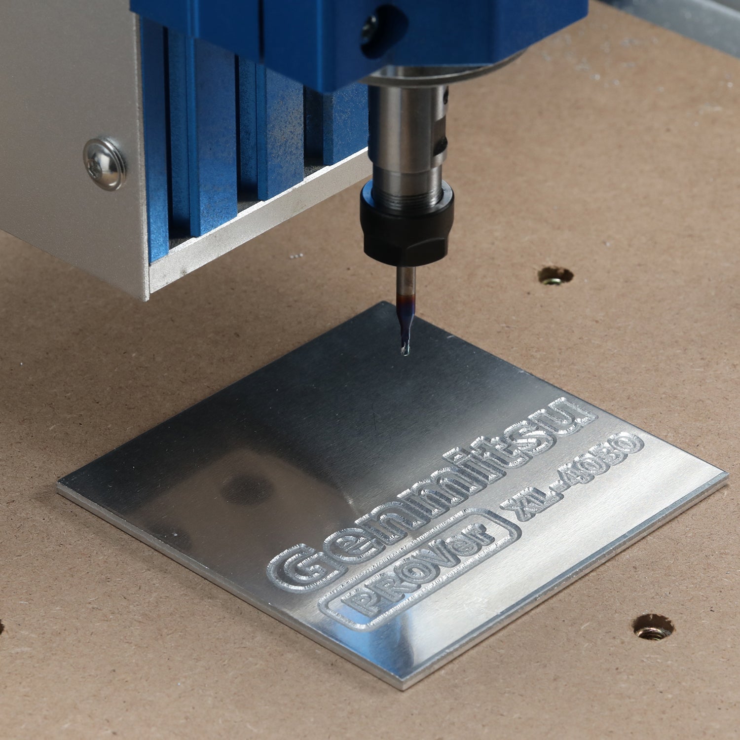
Engraving the spoilboard
Totally optional but I like to use an engraved grid of X Y lines on mine, this is a great help with aligning stock and making sure it is all within the cutting area. The grid lines are spaced by 10mm on both the X and Y axes so this takes a while to engrave.
The work origin for the engraving is at the centre of the cutting area. The easiest and most accurate way to set this is to home the router and then use X and Y jog towards the centre by half of your maximum travel distance, or mark this on the bed by drawing diagonal lines from the edges of the spoilboard, where they cross is the work origin. This is close enough to the centre of the cutting area.
I created a user command button in Candle to move to the centre position. The code is “(Go to Ctr) G53 G0 X-302.5 Y-250 F1500” the G53 says to use machine coordinates and the X and Y values are ½ of my measured cutting area (Adjust the signs if your home position is NOT back, right). The leading comment is useful as when hovering the mouse over the button I am reminded of its function.

Load the surfacing Gcode file ‘6050 Spoilboard Engrave.nc’, the speeds, feeds are set for the stock 300W motor.
- Job: 6050 Spoilboard Engrave
- Stock Size: X=605, Y=500, Z (Depth of Cut)=0.5mm
- WCS Origin: Centre of cutting area, top of stock
- Bit: 20°V bit 3.175mm (1/8”) shank. (from the Sample bits)
- Speed: 12000 RPM
- Feed: 800, Plunge 800 mm/Min
- Heights: Clearance 5, Retract 1 mm
- Rectangular Area Engraved: X=580 Y=480 mm
- Gridline Spacing: 10mm
The lines are intended as XY alignment guides, not as a ruler so there are no numbers on the grid. The centre is marked with a circle and each centre line is marked with a V at the edges to make finding the centre easier. The lines will be faint but that is all that is needed.
Finishing the surface
Remove any surface threads or lips from the lines by sanding, a paint scraper…… I will happily admit to being Lazy, so I used a 25mm (1”) Sanding disk to remove the bits from the engraved lines. This uses the ‘6050 Spoilboard Sanding.nc’ Gcode.
- Job: 6050 Spoilboard Sanding
- Stock Size: X=605, Y=500, Z (Depth of cut)=0mm
- WCS Origin: back, right, top of stock
- Bit: Generic 25mm Sanding disk
- Bit Diameter: 25mm, Stepover: 14.71mm (58.82%)
- Speed: 3500 RPM
- Feed: 750, Plunge 500 mm/Min
- Heights: Clearance 5, Retract 3 mm
- Rectangular Area Surfaced: X=622.68 Y=517.68 mm
- Maximum Cut (with rounded corners) X=630 Y=525 mm
Spindle speed is 3,500 RPM so turn the potentiometer to half and adjust from there but make sure that the spindle motor is not close to stalling.

It uses the same XY origin as the surfacing Gcode (back right) but make sure the sanding disk is only just touching the spoilboard surface (with the foam pad in use if yours has one) and a medium fine grit disk before setting Z Zero. There is no depth of cut used so, if you want more sanding, manually adjust the Z height and reset Z zero before running another pass.
I used to use a 50mm disk but the 25mm one fits into the SainSmart dust shoe and so is much less messy!! Using a sanding disc on MDF is an exceptionally messy process and the dust can be nasty!!!!
The Finished article:

Mounting a Laser
NOTE: The 6050 control board can supply a Laser with up to 4 Amps at 12V (48W input power). Please check the maximum current draw of your laser and if it exceeds 4Amps at 12V then you will need to use an external 12V DC power supply. All of my SainSmart lasers draw 4Amps or less so I am not using any external power supplies that came with some of the Lasers.
I have tried two Lasers, both SainSmart ones;
-
10W Compressed FAC (RFL10W)
- 40mm Laser body with no separate Laser Control Module or power supply
-
5W Compressed FAC (CFL55P-EB)
- 33mm Laser body with a separate Laser Control Module and power supply.
The 10W Laser is advertised as compatible with the 6050, the 5.5W model I am using is not!!! However It is an easy fit.
Laser Control Module Mounting
The 5.5W Laser has a laser control module. I have attached it to the front of the Z axis Stepper mount at top of the Z Carriage with a strip of self-adhesive Velcro making it easy to add and remove. The connecting cables to the laser head allow for any Z movement.
I am using the 3 pin socket on the Laser Control module to provide the PWM signal AND the 12V supply, the external power supply is not needed.
Laser Head Mounting
There are three basic methods of mounting a laser head:
- Mounting Plate
- Inside a Motor Mount
- Something else
I am only going to cover the first two.

My ‘ideal’ position for all lasers is where the focus point of the laser can be set to be just below the top surface of the spoilboard at the bottom of the Z axis travel. This gives maximum flexibility in the stock thickness that can be used and also allows materials to be cut all the way through.
Mounting Plate
The 6050 comes with a Laser mounting plate which replaces the spindle motor mount, the Laser head is screwed onto the mounting plate which is then bolted to the Z frame replacing the motor mount.
All my Lasers have suitable mounting holes at the back allowing them to be screwed onto the mounting plate, this covers all current SainSmart ones. The pictures show the SainSmart 10W Compressed FAC Laser Module mounted. The height can be adjusted by using different mounting holes for the Laser plate as for the 52mm motor mount. Practically there is more flexibility, while there are 4 mounting holes on the Laser plate just using two will hold it quite adequately, it’s not subject to the same stresses as a spindle motor.
Inside a Motor Mount
The Laser head slides inside the motor mount replacing the spindle motor.
A 40mm head will only fit into a 52mm motor mount if it has mounting groves on the inside. The 6050 52mm motor mount does not have these. If you are using a larger motor mount then a mounting sleeve can be used.
A 33mm Laser can be fitted into a 42mm motor mount if it has mounting groves on the inside. The 52 or 65mm motor mounts with the 6050 require a mounting sleeve (see below). Just align the head into the grooves in the sleeve and then slide the head and sleeve into the motor mount. Tighten the motor mount just as you would for a spindle motor. The sleeve and head can be slid up and down within the mount to adjust the height.
Mounting Sleeves
Just a 3D printed sleeve with an outside diameter to fit into the motor mount and grooves on the inside to take the smaller laser head. I have created a series of sleeves for 3D printing (download here) There are ones for fitting a 33mm Laser head in a 52, 65 and 69mm mount and a 40mm head into 65 and 69mm mounts.
My preference is to use sleeves in the motor mount where possible, this means the router should not need to be re-trammed when the spindle motor is replaced. The mounting plate method is more versatile and does not require printing mounting sleeves. If the laser has a shroud, then mounting with a sleeve can interfere with raising the shroud.
Cabling
The cable from the Control box is in the drag chains coming out on the top of the Z frame, the cable is labelled Laser.
At the control box the laser socket connections are, from top to bottom, +12V, PWM, Gnd.
NOTE: Mine is an early model but the wire colours are swapped, the Black cable is +12V, Red is Gnd and white is PWM! Please check yours!
NOTE: I have contacted SainSmart about this and they have said:
- The wire colours on the Laser cable will be changed to Red +12V, Black Ground and White PWM.
- The JST-SM connector needed will be added to future PROVerXL 6050 plus routers or Laser modules.
If yours has already been manufactured, at the time of writing (March 2023), the description below is valid. If not then you can disregard a lot of this. Check the wire colours on the Laser cable at the control box, if from the top they are Red, White, Black then yours is a modified one.
The termination of the Laser cable is a JST SM 2.54mm 3 pin inline socket. This requires an adapter cable to connect to the JST XH plugs normally used on Laser heads and control modules. (You can actually fit a JST-XH plug into a SM socket, but only with care and it is NOT recommended!) The SM connector cable was not included with mine, this will change in the future, but is easy to set up. If you don’t have one included you will need a JST-SM 2.54mm 3 pin plug (Amazon, Ebay….)
The pins on an existing Laser cable can just be removed from the plug (see picture) The actual metal crimp connectors are the same for both the JST XH and JST SM plugs so they can be just inserted into the new SM plug. Before re-inserting the terminals make sure the tab has not been stuck down. If necessary, prise it up slightly with a sharp knife. Do not do this more than a few times or the tab can break!.
You need to match the relevant connections on the router board to the Laser. (Remember to match the cable signals, not the wire colours!)
As I have multiple routers and multiple lasers, which I swap around, I am using a different method which will make things simpler (for me!) I am replacing the socket on the end of the Laser cable with a 3 pin spring connector. (The dots are just a sharpie to show the actual signals +12V, Gnd and PWM regardless of the wire colours) This can be attached somewhere on the Z carriage with double sided tape…. Other connectors such as screw connectors could be used.
Just cut the ends off the relevant cables, strip them and insert them into the connector. (If you have a soldering iron tin the ends, if not don’t)
I need one cable for each Laser which I will leave permanently connected with the correct wire colours (Red +12V, Black Gnd, White PWM). Short cables for a Laser Control Module, ~90mm (4“). Longer cables, ~350mm (13.5”) for a laser head only.
Using the Laser
Before use you need to make sure the Grbl settings are correct for using a Laser and match the CAM Laser software used to create the Gcode.
The critical settings are:
- Set Laser mode $32=1
- Max Spindle Speed $30, match the settings in your Laser Software
- Min Spindle Speed $31, Probably 0, but match the settings in your Laser Software
The button on the front of the control box setting Laser mode does not change these settings, all it does is turn the Spindle motor off, the laser will still work regardless of the position of this button.
If the spindle motor is not disconnected make sure the Laser mode switch on the control box is depressed which will turn off the power to the spindle motor.
Upgrades and accessories
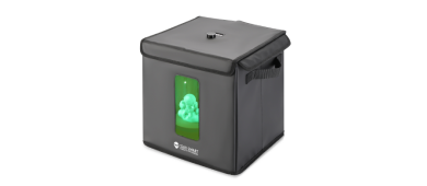
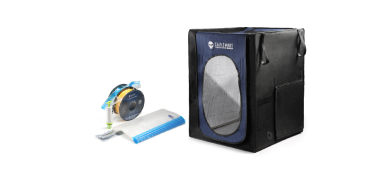
Air Assist for a Laser
Air Assist is using an air pump to provide a powerful airflow to the point where the Laser beam is burning the material, not as necessary for engraving as it is cutting but still useful. The airflow keeps the lens from being contaminated by fumes and soot, and also blows any soot, fumes and debris away from the cut keeping the material cleaner and the laser beam unobstructed which allows a deeper cut.
I strongly suggest getting one if using a Laser. I have a pond pump which works well with a strong airflow (60l/min) but is unfortunately quite noisy and the airflow is not adjustable.
SainSmart now sell Air Assist pumps, there are two versions both with a variable air flow, unfortunately they are not available in all areas. All pumps have to be manually turned on and off, there is no air assist connection on the 6050 motherboards.
With any Air Assist pump check that the tubing diameter is suitable for your laser, the SainSmart nozzles need a 4mm ID tube. The spigot on the Laser is 5mm OD so a 4mm tube will stretch to fit and make a secure connection.
Also check you have a power supply, the 6050 does not provide a suitable 12V DC supply.
If you are using one the tubing clips in the pictures are my design, they will take a 6-7mm OD tube and can be secured with double sided tape and keep things neat and tidy. They are 3D printed (download here).
Spindle Motor
Upgrading the spindle motor is simple. In a 52mm factor the standard 300W can be replaced with third party 500W or higher motors.
The included 65mm motor mount can be used to hold even more powerful motors and routers.
I have not upgraded my spindle motor so I can’t really comment, but the things to consider are:
- Mounting, 52mm or 65mm diameter mounts are provided with the 6050.
- Power, will a separate power supply be needed?
- Cabling, How the cables to the router will be organised?
Dust extraction
I recommend this for a number of reasons:
- Minimises potentially harmful dust and fumes.
- Prevents dust and chips from interfering with the current cut.
- Keeps the router and area clean.
For the 52mm 300W motor SainSmart sells a well designed dust shoe which is suitable for bit sizes up to 25mm (1”) This comes in multiple pieces attached together using magnets making things like changing the bit and setting Zero positions as easy as possible.
You will also need a suitable shop Vac and vacuum hose.
Clamps
If this is your first router securing your stock to the bed/spoilboard is vitally important. If this is not your first you almost certainly know that if the stock moves while being cut the job is ruined.
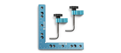
They do have to be used correctly though, assemble as shown (the addition of a 6mm washer under each wing nut makes them easier to adjust) To make them even easier to use I threadlock, or use PTFE tape, to secure the T nut. There is only a little room to adjust the tension by using the plastic knob before the bolt hits the bottom of the channel, tighten the clamp using the wing nut.
The pressure of these clamps must always be down onto the stock, as shown, to hold it firmly.
The SainSmart accessory clamps also work very well on the 6050 and will secure thicker stock, available in 2 sizes: Large. Large clamps (50mm stock) and Smaller clamps (45mm stock)
Cleaning and Maintenance
Always a good idea!
The frequency of maintenance needed is dependent on the usage of the router. Periodic maintenance should include:
- Keep the leadscrews clean, the 6050 keeps most of the dust and chips away but some will still get there.
- Keep all the slide rods and linear rails clean, same as the leadscrews.
- Lubricate the slide rods and leadscrews after cleaning. A dry PTFE spray lubricant is ideal.
- Periodically check all the frame and other screws for tightness. If a screw needs frequent re-tightening, then consider removing it and adding a little threadlock before replacing it.
- Check all wiring to make sure there is no rubbing on the outer insulation and all plugs are still secure.
For cleaning and lubrication to access the Y axis leadscrew you will have to remove the centre slat from the bed, to access the Y axis rails remove the edge slats.