By Graham Bland
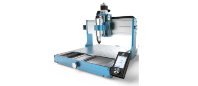
I just received my SainSmart Genmitsu 3020-PRO MAX. My thanks to SainSmart for sending me one to evaluate. Any comparisons with the 3018-PROVer relate to my existing SainSmart Genmitsu 3018-PROVer and the current specifications on the SainSmart Website.
NOTE: The version I have is a pre-release one. I am fairly sure nothing significant has changed but there may be minor details that have been changed.
If you are already familiar with CNC routers a lot of this may be repetitive for you but it is aimed at a first-time user. You may still find something useful here though.
This is a guide to assembling and setting up the SainSmart Genmitsu 3020-PRO MAX, nothing more but there will be other ‘Guides’ on useful things such as what you can make with it at a later date.
This is not a review; I am working on one, but that has to include things like using it, and before it is used it should first be set up correctly.
Unboxing
Carefully cut the packing tape, open the box and take all the parts out of the box! Simple and easy.
Seriously though it is, as normal for SainSmart, well packaged and protected.
Some parts are pre-assembled The Frame and Bed, Gantry, Y and Z axes, all steppers are mounted, there isn’t a lot left to do.

Comparison with the 3018-PROVer
Some comparisons of the non-obvious details with the SainSmart Genmitsu 3018-PROVer (not all PROVers or PROs are the same). I have used both measurements made by me and specifications from the SainSmart website. All dimensions in mm.
|
Item/measurement |
|
Frame Side Rails |
40mm x 40mm (4 screws) |
20mm x 40mm (2 screws) |
|
Front/Back Plates |
10mm x 40mm |
8mm x 45mm |
|
Y-axis Slide Rods |
12mm Dia |
10mm Dia |
|
Y-axis Rod Spacing |
150mm |
150mm |
|
Y-Axis Lead Screw |
8mm Dia |
8mm |
|
Gantry Upright Thickness |
10mm |
8mm |
|
Gantry securing Bolts |
8 each side |
6 each side |
|
X Cross Members |
40mm x 20mm (2 screws) |
20mm x 20mm (1 screw) |
|
X-axis Rails |
2 15mm linear Rails |
2 8mm Dia rods |
|
X-axis rail Spacing |
75mm |
75mm |
|
X-Axis Lead Screw |
8mm Dia |
8mm Dia |
|
Z-axis guide rods |
10mm Dia |
8mm Dia |
|
Z-axis Lead Screw |
8mm Dia |
8mm Dia |
|
Z-Axis Guide rod Spacing |
50mm |
40mm |
|
Cutting travel X Y Z ** |
281mm x 195mm x 70mm |
290mm x 170mm x 40mm |
|
Steppers* |
12V XY:1.5A Z:1.8A |
12V 1.3A |
|
Spindle Motor |
52mm 48V 300W 12,000 RPM |
42mm 24V 75W 10,000RPM |
|
Spindle Collet |
ER11 |
ER11 |
|
Power Supply |
48V 7.3A |
24V 5A |
* I have not been able to find the torque figures for the 3020 Max steppers so have not quoted torque for either machine.
* Conservative settings, all 4 limit switches fitted.
While the proof of the pudding is in the eating (an old Yorkshire saying! When I was a young man I misunderstood the meaning of this saying due to my Mothers Christmas Cake and Christmas Pudding recipes. Both involved large quantities of Brandy as an ingredient) at first impression it is stronger, more robust, more powerful, and more rigid than the PROVer.
Pre Assembly
I am not duplicating the assembly instructions here, they are pretty good, but I will add some checks and hints I suggest you perform before assembling. Even if you identify as male I still suggest you read and follow the assembly instructions!
Pre Assembly Checks
After making all of the checks I found my 3020 passed them all, OK I did tighten a couple of screws a little, but the checks don’t take long and are a lot easier to perform and correct any problems before the machine is fully assembled. I intend to be using it for a long time so the speed of assembly is not that important to me.
- Check all bolts and screws for tightness. Using threadlock on the screws is your choice, it would be tedious to completely remove each screw, threadlock it and put it back so I am not going to bother. But I will threadlock any bolt or screw if I find to be loose just in case. NOTE: Even if you threadlock everything it is always worth checking all the screws and bolts for tightness after using it for a short while and periodically as part of normal cleaning and maintenance.
- Using a square or by measuring the diagonals check that the frame is square.
- Place the frame on a flat surface and check that it sits flat.
- Using a straight edge check that the bed is not warped (this is a throwback to extruded slotted beds).
- Hand wind each of the axes along their full travel. It should take a uniform effort and there should be no feeling of sticking or binding. If there is any problem check the axis involved and make sure the moving parts affected are clean and tidy.
Hints
- The top piece of packaging makes a very handy assembly mat!
- Attach the rubber feet to the bottom of the frame before assembling the bed and gantry, it’s much easier.
- According to the manual the rear upright of the gantry should be 13mm from the back of the frame, I find it easier to measure this before attaching the gantry. Using a ruler and square scribe a line 13mm from the back frame with a sharp knife, rub a bit of pencil into it to make it easily visible. It will be much easier to align the gantry to the line rather than messing about with squares and rulers while assembling.
- Before finally tightening the gantry bolts to the frame use a square to check that the bed and the inside of the motor mount is square both in the X-axis and Y-axis. If not, the gantry can be adjusted to correct this by tilting it forwards or backward slightly or moving one side up or down slightly.
- If you fit the optional bottom Z-axis limit switch, be careful that the routing of the cable keeps it clear of the X axis limit switch.
- When mounting the motor the height in the mount can be adjusted by sliding the motor up and down before tightening. How high to mount the motor will depend on how far the bit you are using sticks out from the spindle and the thickness of your stock including any spoilboard you intend to fit. Make sure that the motor case is not below the top of the mount or above the bottom.
- When tightening the motor securing bolts tighten them both evenly, as you tighten one the mount is compressed and the other bolt may become slack so swap between them while tightening and make sure that both are secure.
- The black piece of sticky labels are wiring identifiers. These loop round the motherboard end of the wires for the Limit switches, steppers, etc. to make them easier to identify when plugging them into the motherboard. Use them or not as you wish.
- Before connecting the cables decide where you want to mount the motherboard, I have mine at the far left of the gantry for 2 reasons. It keeps the USB cable away from the router and my power supply will fit best to the left of the machine and the wires from the power supply are not very long.
- If you plan on swapping the spindle motor with a Laser when ‘tidying’ the cabling leave the spindle motor wires separate from the ‘fixed’ Stepper and Z-axis limit switch cables.
- Do not use tie wraps to hold the cabling around the X gantry cross members apart from at the very ends!
- If, as I am, you are going to sit the power supply place a baffle between the router and the power supply fan intake to prevent any chips and dust from going straight into the power supply. I am using a piece of foam attached to the edge of the power supply with tape.
- MOST IMPORTANT! After the assembly is finished and before you turn it on stand next to it and take a Selfie. It is the last time you will ever see it so clean and shiny!
Assembly
The instructions are good (but read my hints above first!).
Install Candle on your PC, if you have problems with installing it look at https://docs.sainsmart.com/article/7c20d7zaw3-how-to-install-candle-grblcontrol-for-windows
For more details about how to setting it up and run the machine, please refer to this guide. (Download here)


