
Written by Graham B.
This is a guide on installing and using the SainSmart 44mm 24V brushless motor on a 3018-PRO or 3018-PROVer.
I am producing this as a document, mainly because it is an edited
series of notes I made, partly because I am tired of watching instructional videos on YouTube which play at Mach 2
and so I am constantly stopping, rewinding and re-watching. Also I have been told I have a body made for Radio,
a voice most suited to the Deaf and I still haven’t worked out how to use the video camera on my phone
properly.
Motor types
There are lots but just a quick word about brushed and brushless motors. Not going into too many details but a brushed motor has the wiring to create the variable magnetic field required for motion on the inside and the fixed magnets on the outside, so brushes are used to supply the current onto a commutator (round bit with groves) so that as the motor turns by 180 the inner magnetic field is reversed continuing the turning forces. The speed is controlled by changing the voltage applied to the motor.
A brushless motor has all the wiring on the outside and the fixed magnets on the inside so no brushes are needed. BUT (nothing is free) the variable magnetic fields on the outside still need changing as the motor rotates to keep it moving, this job is done by an ESC (Electronic Speed Controller), an external board.
The standard 775 motors on the 3018 and the 300W motor on the 3020 are brushed motors.
The ESC For a brushless motor any automatic control board should take a PWM signal from the Grbl board and apply that to control the speed of the motor.
Specifications and comparisons
The most important dimension of the motor is its diameter, this must match the motor mount on your router. You can’t put a 52mm diameter motor in a 44mm diameter hole and you also cannot secure a 44mm diameter motor in a 52mm diameter hole!
The standard 775 motor, the 20k 775 motor and this brushless motor all fit into a 44mm diameter motor mount.
|
Std 775 |
GS-775MR 20K |
Brushless |
|
|
Mount Diameter |
44mm |
44mm |
44mm |
|
Body Length |
66mm |
66mm |
75mm |
|
Tool holder |
ER11 (fitted) |
ER11 (fitted) |
ER11 (fitted) |
|
Weight |
406g |
406g |
400g |
|
Rated Voltage |
24V |
24V |
24V |
|
Max No Load RPM |
~9,000 |
20,000 |
12,000 |
|
Torque Nm |
- |
- |
0.142 |
|
Noise Level at max RPM |
80.8 |
~90 (Est) |
57.8 |
|
Speed Control |
Variable Voltage |
Variable Voltage |
PWM to ESC |
|
Service life (hours) |
- |
- |
50,000 |
Installing the brushless motor

The motor body is a straight swap for a 44mm diameter standard 775 motor. The only difference is that the cooling vents on the brushless motor body are towards the bottom of the motor but on the standard 775 they are towards the top. Adjust the height of the brushless motor into the mount so that the top of the cooling vents are just below the bottom of the motor mount. Do not obstruct these vents! This will mean that the collet is going to be a couple of mm lower than the standard motor.
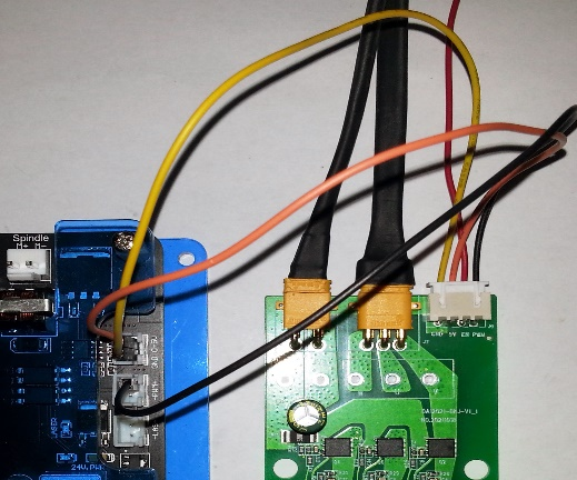
Wiring

The ESC board requires the following
- +5V and ground to drive the control circuitry on the ESC board
- PWM signal to control the motor speed from the router board.
- +24V and ground to drive the motor
- A 3 pin connection between the ESC board and the motor.
NOTE: The pin marked X in the top connector is not used.
Exactly where the 5V supply and PWM connections are made to your router board depends on the actual Grbl board, the pins on the 3018 PRO Grbl board and the 3018 PROVer are slightly different.
The switch on the right hand side of the board controls the direction of rotation of the motor, as shown in the down position the motor will rotate Clockwise which is where it should be set, if in the up position the motor will rotate Anti-clockwise.
There are no LEDs on the board to indicate if power is being supplied.
Direction of rotation
The switch on the board controls the direction of rotation of the motor as in the photo above Down sets the motor to rotate in a clockwise direction, up will change the direction of rotation to anti-clockwise. I would not recommend changing the direction of rotation unless the motor is stationary, no reason I just don’t know what would happen.
Unless you have a specific reason to change this leave it set to clockwise, this is the standard direction.
ESC power and control
The provided cable for the 4 pin connector has Dupont single pin connectors on the other ends which will just slide over the pins on the router board. The unused (En) wire can be disconnected from the socket or just left hanging.
|
3018 PRO |
3018 PROVer |

|
|


|

|
|
The 5V supply comes from the left hand pins at the bottom of the board, marked 5V. The lower pins are Gnd as marked at the side. The PWM signal comes from the middle pin of the 3 pin Laser socket at the top of the board. |
All the pins are on the right hand side of the board. The top 2 pin socket provides the 5V and Gnd, the top pin of the middle socket provides the PWM Signal, this shares a common ground with the 5V supply so only one wire is needed. |
24V DC Motor supply.
There are a number of options here.
All the connectors described here can be bought from a variety of sources, amazon, ebay………. Exactly where will depend on your location. They are all inexpensive and others are available.
Option 1
Connect the existing motor wires from the spindle socket on the router board to the ESC board 24V connections. There are a number of ways to connect but some require soldering.
A

Attach male spade connectors (4.8mm) to the end of the ESC input cable, either crimped or soldered. These can then be inserted into the ends of the existing motor cables allowing the existing spindle motor to be swapped back in if needed. Make sure they are shrouded so that the connectors are fully insulated from each other. Or use extra insulating tape.
B
Connect the ends of the ESC input cable to the back of the existing spade connectors or directly to the wires themselves. These must be soldered to make a good connection. Make sure that these are well insulated with electrical tape so that a short circuit cannot occur. This will require a soldering iron.
C


Cut and strip the ends of the original motor wires and use a spring loaded or screwed connector block such as these to connect the ESC Input cable. The original spade terminators can be re-connected if you want to revert to the original motor. Cut the motor existing motor wires at least 5-10cm from an end for ease of assembly and to allow for replacing the original motor if needed.
D

Attach a JST VH 3.96mm 2 pin connector to the end of the ESC input cable and plug this directly into the Spindle socket on the router board. This will require a crimping tool or soldering iron.
My recommendation would be to use a spring loaded or screwed terminal block, it’s the simplest and requires no soldering.
Option 2
Splice the ESC input cable directly onto the routers power supply. If doing this the original connection to the barrel plug must be maintained as this will still be needed to power the router.
An adapter can be made using these 5.5 x 2.5mm barrel connectors. There are a variety of sizes available so make sure to get the right ones, they must be 5.5 x 2.5mm, the more common 5.5 x 2.1mm will NOT fit.

Plug the original power supply into the female end and the male plug into the router power connector.
NOTE: Before taking this option check where you are going to mount the ESC and that the cable from the ESC is long enough to reach the barrel connector in your preferred location.
This has the advantage of using a steady 24 input voltage from the power supply, not the PWM modulated output from the Spindle connection.
Option 3
Use a separate 24V DC power supply, if you have one lying around, 24VDC (4A or above) this may be the easiest option. If not I don’t think it’s worth buying a new one. A separate power supply will normally end in a barrel connector, so you still need to either splice into the wires or use a 5.5x2.5mm female to screw connector as above. Make sure that the polarity of the supply matches the wires on the ESC power connector.
Whatever solution is used make sure that all connections are good and solid, loose connections will cause arcing which apart from giving poor performance and possible damage to the control boards will generate heat and sparks and can cause fires. Also ensure any connections are well insulated to prevent any short circuits.
NOTE: It is very important to ensure that the polarity is correct, + is connected to + and - connected to -. The barrel connector on the standard power supply is centre pin +ve and outer casing -ve. If you are splicing the wires on a power supply it is probable that they are both the same colour so check the polarity using a multimeter.
Mounting the ESC board
Whatever way it is mounted it is imperative that the board components, especially the connections on the bottom of the board, are insulated against any contact with the router frame as this will cause short circuits, damage the board and could start a fire.
There are a number of options here, there are four 10.25mm mounting holes on the ESC board. The smaller holes in the board are unused connections and must not be used for mounting!

I have used adhesive Velcro to secure the board, a large piece across the back of the board to fully insulate it and 2 pieces on the back of the top and bottom X axis rails. The Velcro is thick enough to prevent any of the rear contacts working through and shorting on the router frame. I would not trust double sided tape by itself to maintain the insulation needed.
You could use bolts, T nuts and some insulating spacers or use double sided tape to secure the back of the ESC board to an insulating layer, thin wood, Plexiglass, even thick cardboard would do. Then more tape to secure the insulating layer to the frame. If you decide to use T nuts and bolts I would use two and make sure the bolt heads/washers do not contact any components on the board. You could also use plastic spacers to keep the contacts on the back of the board away from the frame rather than a solid insulating piece.
I have more than one router and may swap the motor round to a different one, so Velcro rather than double sided tape makes sense to me, this is also the way I attach the Laser control module when using a Laser.
Mounting the Motor
Just slacken the screw, slide out the old motor, slide in the new one and re-tighten the screw.
The vertical position should be with the top of the vent slots just below the bottom of the motor mount.
The Motor can be slid further down if required but do not block these vent slots with the motor mount or it could overheat and fail.

First Impressions
Silence is golden
But my bit still
turns
Silence is golden, golden
But my
bit still turns.
My apologies to the Tremeloes and any music lovers.
Initial operation tapping directly into the power supply.
It is almost silent, very quiet to the point that I have to look at it to see if it is rotating.
Minimum speed seems to be 950RPM using $30 of 10,000, check once max no load speed checked/calibrated. Anything below this and it stops. But at 950RPM still produces a decent amount of torque (not measured accurately as I don’t have the equipment) But when did you ever want to use a spindle speed that slow?
Using the 24V router motor supply
No visible change under no load


2 comments
Is there any PWM frequency requirement?
One thing I would like to know how many Watts this spindle is.
I have this on my 4040-Pro using the PWM where the laser plugs in and a 24V 15A power supply. It works a treat and is indeed very quiet.